Announcement

Collapse
No announcement yet.

Plasma Ignition | Plasma Jet Ignition

Collapse
X
 
  • Filter
  • Time
  • Show
Clear All
new posts

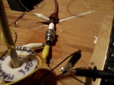
  • Here is a video https://www.youtube.com/channel/UCWc...trhnbrB9ZsE0OQ of the latest spark experiments.
    All the lights is lighting up for each spark. I think it is because of the BEMF from the spark gap. How do I stop the the BEMF? I feel I am so close....
    Last edited by ThankyouBedini; 04-16-2015, 03:15 PM.

    Comment


    • Originally posted by Mika View Post
      Ok, thanks, I'll test that soon. These are the components I'm going to use. 200w 220v inverter, 50A 1000V bridge rectifier and two 450VAC 50/60Hz 4uF caps, maybe I'll order two more of those too. Four 100 ohm 100w power resistors also, but they have not yet arrived. Do these seem right kind of parts?
      Hi Mika, I will report what I understand about your components:

      - BRIDGE RECTIFIER - should handle the inverter. Watts DIVIDED BY Volts = Amps = 0.909A. It could work if its diodes' are able to open and close fast enough at the charge/discharge rate required by the ignition HV spark rate.

      - CAPS - charge to 4uF AND discharge fully 50/60 per sec at 450v, so the charge will be lower with 220 inverter output. Potential charge will also reduce as the spark events increase past 50/60 a sec.

      I'm not shure how and exactly where you want the resistors to be in the circuits?

      I'll explain the HV plasma event in next post...

      What is important is to know what HV polarity your coils fire, because your HV diode strings will need to protect caps > bridge > inverter and if diode string is WRONG WAY parts will blow.
      Last edited by Willem Coetzee; 04-18-2015, 12:09 PM.

      Comment


      • Negative Resistance

        Originally posted by Mika View Post
        Hey can you tell me will this plasma ignition fix misfires too, or will it only make a plasma spark "after" the original ignition parts get an ordinary spark through first? If you understand what I'm trying to say...
        Hi Mika & ThankyouBediini,

        Aaron has explained NEGATIVE RESISTANCE and TIME COMPRESSION in this thread, and his explanations are the best for me to understand. But let me attempt to answer your questions:

        The HV DIODE STRING gives HV an alternative path to ground with LOWER RESISTANCE than the path over the spark gap.
        So HV will of cause try to go the Low Resistance path first, but the HV diodes slams shut, and the HV bundles up against the HV diodes. It "splatters" in a 90 degree direction perpendicular off the wire, finding no ground in the air or nearby 360 around the wire. If it did, it would've jumped to that ground and no plasma or spark in the spark gap.

        But now the only other path for the HV to ground is over that spark gap, and it recoils away from the HV diodes at tremendous speed in the OPPOSITE DIRECTION along High Resistance path over the spark gap to ground.

        This "hv" has also hereby in this same time ran right around the circuit over the spark gap through ground right up to whatever LV source.

        This new type of "hv" has overcome all the resistances of both the HV and LV paths to the spark gap, running not "in" the wires but 360 degrees around them, like a radio broadcast and reception wave.

        And this gives the appearance of a "hv vacuum" or NEGATIVE RESISTANCE that sucks "current" or Radiant Energy, or Aether, INTO the spark gap.

        There actually is no "vacuum" or "negative resistance" but it causes this whole sequence of events to happen in such a short time (Mark Mckay clocked it at 10 nano seconds) that it is as if a TIME COMPRESSION occurred.

        The "spark"' event no longer progress to a spark, but all the energy gets sort of bundled-up in and explodes out at the beginning of ionizing the gap, accelerating the ionization so much that the gas mix in the gap expands into the 4th-state of mater: plasma.

        A plasma cloud has a full chance to get in contact with ground as its volume expands over and beyond the electrodes thereby properly obtaining ground contact.

        As you can see this gives a high possibility also for no misfires, and also eliminates cycle-to-cycle spark variation. Over and above more complete fuel combustion, this is also responsible for more torque, because there is no 10-30 misfires out of every 1000 firings that wastes fuel not converted to crank driving.

        Charge from capacitors is NOT what makes this new type of ignition event - capacitor discharge merely boosts the Lorentz-force responsible for getting the plasma away from the plug electrode and shooting it deeper into the cylinder space, which is also desirable for more efficiency and power, but the more capacitance into the gap the more the plug electrodes wear down.

        No matter how big additional capacitance, it will not in itself help to cancel misfire, because it needs HV, and if the HV is NOT boosted per the Murakami-method, it cant jump the spark gap every time all the time.

        What "negative resistance" then means is that over and above no resistance from a conduit, the power is also delivered in LESS TIME - so any conduit can be a negative resistor IF a discharge is performed over it per the Murakami Ignition Method.

        You can say that the resistance of a normal conduit or component is "positive" because its dynamics CONTRIBUTE to reduce current flow and/or increase voltage drop.

        But "zero resistance" is just Zero Ohms - it is NOT "negative resistance" - so it should rather be called "neutral resistance" because it neither ads nor takes away resistance. It does not alter source voltage or source current. This is like super-conductivity.

        With a true "negative resistance" you will have the power delivered in MUCH LESS time, (in case of ignition, 10 times faster than CDI, and 100 faster than Kettering) which is an artificial BOOST of Watts. Thats WHY...
        - spark plug electrodes can corrode faster. Oxygen in plasma state oxidize the metal faster.
        - thin wires can't hold such a power pulse - the metal is evaporated - explodes.

        That's WHY Aaron uses non-resistor TUNGSTEN electrode spark plugs, because when he builds a system, he drastically eliminates as much electric resistance possible, use ultra-fast switchable diodes and lower farad caps, to obtain the highest possible HV or RE discharge.

        Aaron also explained pre-ionizing atmospheric intake-air - activated nitrogen from air grabs some free reactive plasmatic-oxygen in the ignition event. (he doesn't say so, but this could maybe help reduce metal oxidation of spark plug electrodes and other metal parts in the combustion chamber?)

        So, the discharging of a small capacitor charge can be accelerated to such a speed that its output pulse gives the same or higher Watts than a higher charged capacitor at the same charge voltage discharged normally. I think same goes for coils.

        SO... whether the true Murakami Ignition is used, or booster cap method taught by Aaron, plasma will be there, and is more an more visible the higher the cap charge... BUT... mind the amount of capacitance discharged at these speeds.

        Hope this helps a bit.
        Last edited by Willem Coetzee; 04-18-2015, 03:48 PM.

        Comment


        • Thank you a lot Willem!
          Your post for sure helps. I for sure understand how the different cap values affect the circuit and how it take time to charge bigger uf caps. I now also understand the difference between the Murakami plasma ignition method, and the booster cap method.
          From the last video I posted you can see how the lightbulbs light up as the spark happens. The 25 watt lightbulbs (more resistance than 100 w lightbulbs) are in series on the wire that goes from the ground on the MOT, to the AC part of the 10 kv FWBR. To my understanding the lightbulbs light up because of the radient energy coming from the spark gap. Tesla said that we have to stop the reverse current. So, the way I see it now is that I have to block or choke the BEMF or Recoil or Aeter or Counter EMF or what ever energy spike that cause the lightbulbs to light up so that all the energy is held in the spark gap and is not flowing down some wires....Click image for larger version

Name:	No Reverse current.jpg
Views:	1
Size:	24.4 KB
ID:	46994
          What Aaron is doing here is what I want to do. How exactly do I do that, or how can it be perfected?

          Thank you all very much.
          Last edited by ThankyouBedini; 04-18-2015, 09:33 PM.

          Comment


          • Originally posted by ThankyouBedini View Post
            Thank you a lot Willem... I have to block or choke... what ever energy spike... so that all the energy is held in the spark gap and is not flowing down some wires....
            Your welcome!

            Aaron has shown a diagram of MONO-directional flow of both HV and LV achieved by his ignition method - HV flows in ONE direction from HV (+) secondary coil output terminal, right around, over the gap, "anchoring/grounding" (or whatever) itself at LV (-) capacitor terminal.

            Normal understood electricity physics is only used by CDI to create sudden magnetic flux on primary - and that's the last time normal (+) & (-) is seen.

            With the HV diodes connected per the Murakami Ignition Methode, the moment the speed of those primary coil flux lines achieve HV on the secondary coil, the LV Cap-&-Primary Coil circuit STOPS working like a normal CDI works.

            Mark McKay's oscilloscope shots show that there is NO "two-way oscillation" between (+) & (-) across the X-access, but a distinctive "tesla-type" saw-tooth discharge graph line: HV-spike, which then drops from peak HV-gap-breakdown-voltage to LV-voltage level taking around 10 nanoseconds, then LV-level line curving in one continual bow for around 100 milliseconds to Zero-Volts finally... NO OSCILLATIONS.

            The Murakami setup creates the specified sudden HV pulse reflected right around from HV to LV as said above and previously explained, and in that state, opens aether/RE or whatever INFLOW around both the HV & LV conduit space, causing HV RE flow on the HV wire into the gap, and LV (RE/Ather/volts) flow along LV (-) ground wire also to gap.

            We are igniting HydoCarbon Fuel, not water. We crack the HC-molecule with the HV/RE and make THERMAL EXPANSION ENERGY with the LV/RE as the cracked Hydrogen and Carbon binds with Oxygen.

            Putting that choke in the LV-ground-wire did NOT STOP the aether from creating electrons (or whaterever that LV is) as it strikes metal surfaces and conduits, but DID change the RE emission frequency (or whatever that is called) to make GREEN PLASMA.

            True Tesla discharge is NEUTRAL, and only when it strikes METAL does it INDUCE currents INTO the metal that it strikes, and THAT current flows to EARTH - the Planet Earth.

            An engine is NOT grounded to Planet Earth, but the Murakami Ignition System one-flows RE into the spark gap from TWO sides - each running One Way - to the gap... where it does a much better job of HC & O cracking.

            We are not driving an electric motor with this, so do not need a real Planet Earth ground, but "airially" ground the (+) and (-) portions of flow in the combustion chamber, so to speak. So yes, like Aaron said previously, you can drop the Farrads, since we actually work with "voltage power".

            The HV-diode does exactly the same for the CDI method and the booster cap method, but the speed of the initial flux generation determines the magnitude of the event, which the CDI on ignition coils stil does faster than Kettering Transistor Switching (all modern OEM ignition systems). Look, OEMs are getting very fast, and they even put the coils straight ON the spark plugs, cause many of them hold plasma ignition patents, and very well knows it is better than standard ignition - they just don't have an inexpensive method.

            Hope this help to also put Aaron's system in better perspective in the big scheme of things, and hope people understand better how important it actually is.

            PS: Hydrogen burning becomes efficient to the extend that the air is pre-ionized BEFORE it enters the engine - Tesla also used activated Nitrogen as "electron extractor". Tesla, Gray, Meyer... all employed Nitrogen - 80% of our atmosphere is Nitrogen... its free... and using it CORRECTLY starts with Plasma Ignition done right - I don't care if some "specialists" disagree. Aaron spells it out if you read Ignition Secrets and Water Fuel Secrets together with the treads.
            Last edited by Willem Coetzee; 04-20-2015, 01:21 AM.

            Comment


            • Thanks Willem for making things more clear for me.
              I understand the Murakami Method pretty good, and how that is used to ignite hydro carbons. The booster cap method is what I am now trying to get a better grasp of because I am not so much into igniting hydrocarbons . Obviously there is a lot of wasted energy when all my lightbulbs are lighting up. It is that energy I would like to keep in the spark gap, and not have is running away. I know it is has to do with making a choke of some kind, but I don't know how to make it.
              I am guessing the choke has 4 wires and a ferrite core. The idea could be to have the radient meet an opposing magnetic field created by the one AC leg from the MOT to the FWBR. When the radient comes back it will crash into that induced field and bounce back to the spark gap, or something like that. Not quite sure. What I have observed is that TheOldScientist on youtube, and 1s9a9r9m on youtube and Aaron are all using a choke with 4 wires in it.
              5:44 in is a 4 wire choke.

              Thank you very much.

              Comment


              • HI All,
                I have a question and that is where can I get information on the "Murakami Ignition Methode,"?

                Comment


                • Hi Ron,

                  http://ignitionsecrets.com

                  Thanks,
                  Aaron
                  Aaron Murakami


                  You never change things by fighting the existing reality. To change something, build a new model that makes the existing model obsolete.” ― Richard Buckminster Fuller

                  Comment


                  • Hi all,

                    Thanks for all of that William.

                    ThankyouBedini - did you get the booster cap to work with a wasted spark ignition coil? It's guaranteed to work.

                    Booster cap is just the cap with diodes in parallel with a plug without the CDI into the primary. It works. NASA, Princeton, the auto makers, etc... all have patents on that method by itself for the plasma. I'm partial to my method and biased of course, but it is superior to theirs in several respects. It has a higher initiating voltage from the CDI. That overcomes higher compression, more ionized gap for more reliable discharge of LV cap discharge across the cap, etc... can be done with off the shelf CDIs. Their method needs a custom build cap charger, which almost nobody is manufacturing. Aquapulser, etc... has some and some other companies but Arvind is the ONLY one to deal with regarding that method - the rest involved with that method, well, you should turn the other direction and run as fast as you can.

                    Anyway, with my booster cap, I conceived of it without having ever known there were patents on the regular cap in parallel with gap method. I used it simultaneously with my CDI/diode method. Variac powering MOT and that output to caps in parallel with the plug while my primary CDI/diode method was used, so was hybrid you could say.

                    That video you show is interesting. I saw the wires wiggle and instantly in my mind, I had a motor, which I built:


                    Anyway, with inductor, plasma is silent and green. Without is loud and white.


                    Eric Dollard is at my home for the past week and a little longer from now and talked to him about it. Learned some Heaviside terminology for what is going on... RECEPTANCE is a negative resistor and ACCEPTANCE is negative conductance. That is what is happening in the circuit and the cap discharge is ABSOLUTELY getting accelerated. That is all in Eric's Symbolic papers dealing with the Generalized Electric Wave. There are definitely novel things regarding the CDI/diode method I came up with so the cap is used simultaneously as the input to the primary of the transformer and as the low voltage source over the gap.
                    Attached Files
                    Aaron Murakami


                    You never change things by fighting the existing reality. To change something, build a new model that makes the existing model obsolete.” ― Richard Buckminster Fuller

                    Comment


                    • Originally posted by Aaron Murakami View Post
                      Hi all,

                      Thanks for all of that William... ThankyouBedini - did you get the booster cap to work with a wasted spark ignition coil? It's guaranteed to work.
                      .
                      Hi Aaron,

                      Everybody please learn to understand HIS booster cap method Aaron explained above. Guys it really IS exactly as simple as that. And its success is in building it exactly like that. I had mine build exactly like that, and the only reason I didn't use an off the shelve CDI for the booster cap charger is that decent quality (like MSD) is very expensive in South Africa, being imported from USA.

                      In the last 6 months since we started contemplating the waste spark plasma issue, I discovered one major mistake in my booster cap unit's setup: the MMC cap (-) and charge circuit (-) was common grounded on battery (-) - so with engine ground also connected to battery (-), I have no clue what the heck happened in the starter solenoid and starter motor every time I started that car up. BUT... it eventually lead to one time having to have had fuses and relays replaced in the fuse box, and the second time it cost me a new starter. Maybe that erroneous way of grounding the charger's ground came from confusion on exactly WHERE ON THE ENGINE the best place is to ground my booster's LV output.

                      If you can give me, ThankyouBedini and every one here a short lesson here on that, I'll have my booster cap unit installed on my waste spark ignition THIS weekend, and be able to take photos and a vid or 2 to help others too.
                      Last edited by Willem Coetzee; 04-21-2015, 12:54 AM.

                      Comment


                      • Aaron and Willem, thank you very much for sharing your knowledge.
                        Today I was experimenting with using my High Frequency Generator (violet ray) to make the HV spark. That works very well, and it is cheap, only 92.99 USD on Amazon. It gives a longer spark than any ignition coil I have ever tested. I got into alternative energy because I first learned about medical suppression. The Violet Ray (it makes ozone) was my first health device, and I would never want to live without one now. Tesla figured it out. The Violet Ray is also a very good tool for visually learning about High Voltage.
                        I learned today that the circuit works better when I use five 25 watt (has more resistance in each bulb than the 100 w) lightbulbs instead of 100 w lightbulbs. Without any bulbs it does not work so good because the boostercaps stops fireing after about 1000 v. My two 4 uf 1800 vdc caps are in parallel, that works better than in series.
                        The spark produced it very bright white and it gets louder when I spray water on it.
                        I am at the point in my research where I am looking for the green light like Aaron is showing. What would be the best way for me to learn how to do just that? Is it just a special way of winding a coil? I am very willing to pay to learn the art of negative resistance. Any books I should buy? Any donations I could do?
                        Any videos out there that I have missed? Please let me see the light!
                        Thank you all!
                        Last edited by ThankyouBedini; 04-21-2015, 08:03 PM.

                        Comment


                        • ThankyouBedini, you have an interesting project that you experimenting with, and I'm sure you are learning lots of things. If your HV is (+) on spark plug center electrode, and you connect your booster's (-) LV output on the spark plug base (the line with the globes on it to get rid of electrons?), and you substitute the globes with a coil from a old relay or something, you might get the green plasma.

                          Just they way I got myself to understand the green plasma is that the HV (+) pulse reaches the LV capacitor and have the cap output to spark plug base "retarded" by the inductor and then the inductor suddenly releases all its energy into the spark gap.

                          With the green plasma setup, Aaron connected the LV output (that usually must go straight to spark plug base) to the one pole of an inductor (like a relay coil or other small inductor) and connected the output pole then to the Spark plug base. So that inductor is in serie between your booster cap output and spark plug base.

                          Aaron will be able to tell us which plasma, the green or the white/blue, gave him the best kick for his gray tube investigations - I do not know what the effect is on combustion though.

                          Just looking at different colors plasma in atmospheric air and pressure gives one no indication of the effect it will have in an internal combustion engine. What is known is that the green plasma system has a "motoring" or "anti-gravity" effect on the LV wires and that inductor, so maybe some of those traits are duplicated in the gas mix in a combustion chamber, but will the effect be on the gas mix or the metal parts or both or none...

                          I can hookup an inductor in my booster cap unit's output to ground, and have a switch so I can switch between blue/white and green plasma while it is on a dyno, and that way obtain real-world data for everybody.

                          The only thing I'm stuck with is WHERE is the best place to ground the LV on the engine... because I'm sure I inadvertently actually sabotaged the efficiency of my unit by the way I "miss-grounded" its LV output it in my previous car.

                          Coming to think of it, I might as well install the blue & green plasma switch in any case, because I've been curious about that myself for a long time, and it will give good data when I start on the next projects like air ionization, and things down that path.

                          Comment


                          • If you're making the plasma, you already have a negative resistor - it's at the gap.

                            You can just put some kind of coil in series between the negative ground and the gap and should get the effect. No special coil. You only want this if you're looking to experiment with this as a way to charge an inductor for a motor but not needed for the plasma ignition.

                            The original reason why I put an inductor there was because I was seeing if the inductor would limit the current from the source but still allow the plasma. If less electrons entered the gap, then would the hydrogen from the air or water ignite without recombining with oxygen (because of reduced amount of electrons) in order to keep it from imploding afterward. The noise is the implosive clap of the h & o recombining into water as it shrinks in volume. With the inductor it does make the plasma go silent so perhaps it actually is helping to prevent the formation of water afterward. So many tests to do and so little time.

                            Originally posted by ThankyouBedini View Post
                            I am at the point in my research where I am looking for the green light like Aaron is showing. What would be the best way for me to learn how to do just that? Is it just a special way of winding a coil? I am very willing to pay to learn the art of negative resistance. Any books I should buy? Any donations I could do?
                            Any videos out there that I have missed? Please let me see the light!
                            Thank you all!
                            Aaron Murakami


                            You never change things by fighting the existing reality. To change something, build a new model that makes the existing model obsolete.” ― Richard Buckminster Fuller

                            Comment


                            • Originally posted by Willem Coetzee View Post
                              Aaron will be able to tell us which plasma, the green or the white/blue, gave him the best kick for his gray tube investigations - I do not know what the effect is on combustion though.
                              Yeah, that is exactly what I'd like to know is effect on combustion.

                              And with the green light itself - is it digging into the copper to get the color, is it some Rydberg Atoms that some are claiming it is producing or is the green light related to Coronium, a pre-hydrogen aetheric element like what is seen in one of these discharge tubes demonstrated by Eric Dollard?
                              Aaron Murakami


                              You never change things by fighting the existing reality. To change something, build a new model that makes the existing model obsolete.” ― Richard Buckminster Fuller

                              Comment


                              • Originally posted by Aaron Murakami View Post
                                Yeah, that is exactly what I'd like to know is effect on combustion.

                                And with the green light itself - is it digging into the copper to get the color, is it some Rydberg Atoms that some are claiming it is producing or is the green light related to Coronium, a pre-hydrogen aetheric element like what is seen in one of these discharge tubes demonstrated by Eric Dollard?
                                Hi Aaron, there can't be a green plasma "from copper" if the spark plug electrodes consist of other elements, like you said elsewhere many times before (unless you discovered a new metal transmutation method or something) - 
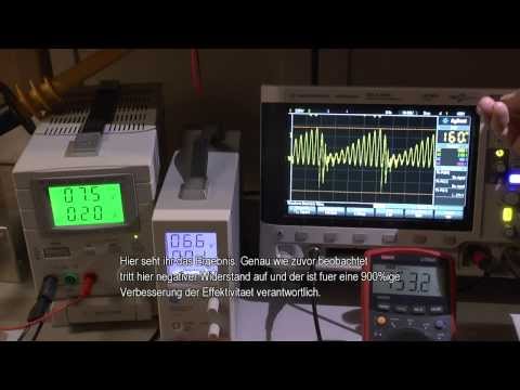
I'm sure Erick will shed some light on this when you guys get time to chat about this.

                                I got 2 blown desktop computer power units and a 17" CRT pc screen available that I can source for small inductors, and wire it parallel to my cap booster unit's ground with a manual switch between normal ground and "inductor ground", so I can put it on a professional dyno that can gives data like the difference in exhaust emissions, and if there are any difference in power/torque. Hopefully I can also find a dyno center that has equipment for the injector fuel supply and return to tank unit in the car to measure any changes in fuel efficiency.

                                What is the best place on the engine to connect my booster's ground?

                                I think I made a very bad connection on my previous car - for some reason I grounded it onto the batter (-), and battery was grounded to both the gearbox and chassis. So booster (-) output ran via battery ground, over gearbox, over engine block, to head, to spark plug bases in head...

                                And here I tell everybody to have the least resistance possible for conduits... hypocrite!

                                As far as I know the ground pulse might be running over the metal and not through it. but if you connect it in the middle of the 4 cylinders to some head bolt or something, the distance to no. 1 and 4 cylinders is more than the distance to no. 2 and 3 cylinders... WILL THAT NOT CAUSE DIFFERENCES IN PLASMA EFFICIENCY?

                                I saw a diagram of Okada Plasma where they merely connect the ground wire to the head nut that is the most central to all the cylinders.... but I have never actually seen where a Murakami system's or cap booster's ground output should be connected onto the engine.

                                Would a same-length parallel ground wire "network" connected to EACH bolt just above the spark plugs not give MORE EQUAL & STRONGER distribution of the ground pulse for the 4 spark plugs?

                                I know how fast these pulse are executed, and maybe standard science with "it will not matter where on the engine the ground is" might still hold true, but remembering your own very meticulous and upgraded wiring you did in the vids for your Subaru's installation, maybe you can give some advice, please?

                                Comment

                                Working...
                                X