Announcement

Collapse
No announcement yet.

Plasma Ignition | Plasma Jet Ignition

Collapse
X
 
  • Filter
  • Time
  • Show
Clear All
new posts

  • Drawings, Diodes and Capacitor questions

    Hello all.

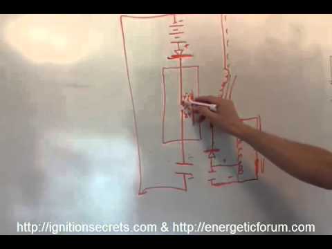
    I haven't done much with the engine this past week but I did manage to diagram a couple different versions of the bench-top demonstration unit. (see attached)

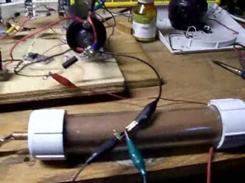
    I have always had some issues with this particular setup either misfiring or relay contacts sticking even with just an 80mfd capacitor which is why I am running a 47mfd capacitor at the moment so it doesn't always provide quite enough discharge so system 'misfires' sometimes. It's a catch 22 situation because smaller capacitor not quite enough so it misfires sometimes and larger capacitor tends to make relay contacts stick so it misfires anyway.

    The original build of this unit has a pretty light duty relay with contact ratings at only 10 amps 30vdc so I intend to beef up this relay with one rated at 30 amps.
    And I intend to just use cheap off-the-shelf auto parts as much as possible for best availability and easy to replicate by replacing the 555 velman timer kit with a turn signal flasher and a SPDT relay.
    I can actually get five of these relays, with pigtail harnesses for only $13.95 delivered:
    http://www.amazon.com/gp/product/B005HFYE1O/

    Then a three pin flasher is only $8.99 delivered.
    http://www.amazon.com/gp/product/B008C9YJ6C/

    These are really common auto parts that can be found at most auto parts stores and even a few department stores and truck stops.

    Then I was thinking about the high voltage rectifier. I have a few of the 30KV 2 amp "ham radio" diodes but I have been working on microwave ovens for over 30 years and I remembered there actually is a heavier duty version of these appliance diodes that everybody has been using. This version of a microwave oven HV diode is rated at 16Kv and 2 amps and is only $8.41 delivered-
    http://www.amazon.com/gp/product/B00HGALV4Q/

    Questions for Aaron-

    What is the type, capacitance and voltage rating of the capacitors you had used for your booster cap bank HV transformer?
    I appear to be experiencing difficulty finding any reference to these component specifics in your videos and documents and specific part numbers would be nice.

    For example; if I wanted to merely replicate your original lawn mower experiment without spending a lot of money on a CDI system, what are the specific values and part numbers for the components including the SCR, Diodes, Capacitors and Resistor bank and can you diagram it?

    Also wondering-
    Is there a specific reason for using polarity specific electrolytic capacitors?

    I have microwave capacitors on the shelf and even though rated for "AC"; these capacitors will hold a static DC charge although, at around 1uf or less; capacitance is pretty low on those.
    I do have what appears to be a motor capacitor rated at 4uf (440vac) and this produces a pretty good result in the same test bed so I have to wonder; why not try these types of non polarized, 'large can' capacitors?
    Such as this-
    http://www.amazon.com/gp/product/B00E6OPHFY/

    Is it possible these may actually charge faster and be less of a load on the AC source for this test bed?
    They are rated for AC but they will accept and hold a static DC charge and are certainly built for durability and I do wonder if they may actually charge and discharge a little faster compared to an electrolytic of similar values?

    Just some thoughts anyway.

    Kindest regards;

    }:>
    Attached Files
    Last edited by Scorch; 05-09-2015, 02:52 PM. Reason: Fixing Image Sizes

    Comment


    • Originally posted by Scorch View Post
      Questions for Aaron-

      What is the type, capacitance and voltage rating of the capacitors you had used for your booster cap bank HV transformer?
      I appear to be experiencing difficulty finding any reference to these component specifics in your videos and documents and specific part numbers would be nice.

      For example; if I wanted to merely replicate your original lawn mower experiment without spending a lot of money on a CDI system, what are the specific values and part numbers for the components including the SCR, Diodes, Capacitors and Resistor bank and can you diagram it?

      Also wondering-
      Is there a specific reason for using polarity specific electrolytic capacitors?

      I have microwave capacitors on the shelf and even though rated for "AC"; these capacitors will hold a static DC charge although, at around 1uf or less; capacitance is pretty low on those.
      I do have what appears to be a motor capacitor rated at 4uf (440vac) and this produces a pretty good result in the same test bed so I have to wonder; why not try these types of non polarized, 'large can' capacitors?
      Such as this-
      http://www.amazon.com/gp/product/B00E6OPHFY/

      Is it possible these may actually charge faster and be less of a load on the AC source for this test bed?
      They are rated for AC but they will accept and hold a static DC charge and are certainly built for durability and I do wonder if they may actually charge and discharge a little faster compared to an electrolytic of similar values?

      Just some thoughts anyway.

      Kindest regards;

      }:>
      I had a series of capacitors that were 330uf and a couple hundred volts each. The rectified MOT output charged that string of caps up to 1100 or so volts max at whatever capacitance divided by how many caps. That was the cap bank I used the most with the booster cap big blast experiments.

      For the lawnmower, I honestly wouldn't go that exact route. It worked great, but limiting current was a problem and we kept burning up some power resistors. The AC was 1/2 rectified to the cap, which was I believe 47uf and a few hundred volts. It would then be charged to maybe 160 volts peak from the rectified AC, which is typical. The SCR I'd have to look up but it was a 600v scr I believe. Diodes were 6A100 (6 amp 1000v). The resistors were 100 ohm ceramic wire wound power resistors from radio shack. Better to use a bigger ohmite power resistor. The gate of the SCR was triggered by a reed relay where we only used the reed connections... one to ground I think and the other lead to the gate. It was on an adjustable plate so we could adjust timing. The magneto magnet on the flywheel would come by and trigger that reed and that is what dumped the cap to the primary of the ignition coil.

      That test was just to prove the point that we could turn the gas main jet all the way in and fully throttle it at max speed with only fuel coming from the idle jet. That was like 7 years ago or something so I don't recall all the details. I do have it written up somewhere.

      Electrolytic caps is what we used for everything - like photo flash.

      For my motor test, I used 4000v 2uf caps - a single one charged up to 1100 volts or so at max. That was a very old oil filed one I believe. That is in the videos I posted of the plasma discharge motor.
      Aaron Murakami


      You never change things by fighting the existing reality. To change something, build a new model that makes the existing model obsolete.” ― Richard Buckminster Fuller

      Comment


      • This plasma booster amplifier wiring setup is for single / sequential ignition firing ignition, like I had on the 1.4 Fiat Uno, an engine with a distributor, and not for Coil-on-Plug or Wasted Spark ignition.

        But if the spark plug lead pares are to be hooked up parallel onto the HV PLUS pole of each Wasted Spark Coil Pack, the capacitor (-) output from the booster would need to be some how hooked-up in a way that gives way more efficiency, than the WRONG way I did it in as I posted 3 posts earlier.

        Is the best solution to connect the booster cap (-) to each spark plug base...?

        OR

        Is it OK to connect the booster cap (-) to the engine head nuts nearest the spark plugs...?

        OR

        Doesn't it matter if the booster cap (-) wire is just kept short and just connected to an engine head nut closest to the booster unit..., and if so would each spark plug base still get the same amount of "hot current"...?

        Point is, although the initial HV event might produce the same HV volts on every spark plug, if each spark plug is not getting the SAME booster (-) output on the spark plug base, the PLASMA effect and the LORENTZ effect might be less on the spark plugs that get less "hot current".

        Or would it??? Thus the 3 questions...
        Attached Files

        Comment


        • Aaron, here's a working model of the plasmajet sparkplug. Works great, have more dies and molds to make,and testing. Imagine the Firestorm inside the tip of the plug,exiting 2.5 mill hole Sounds great. avaiablehttps://www.youtube.com/watch?v=9nddS7YFdBQ

          Comment


          • Scorch's Timing System Udate Video

            Hello all.

            I just produced another quick update video for the progress of my custom timing system being installed on a cheapo generator for the purposes of eliminating the waste spark and providing for easy timing adjustments to the CDI system.

            I originally planned to just use a hall sensor or reed switch but then decided to become a lot more picky about precise timing so I merely modified an off-the-shelf timing "reluctor" cam (LX104 $6) and magnetic pickup (LX102T $13) as found in many automotive applications and readily available at any auto part supply and easily connected any Capacitive Discharge Ignition system.


            That is for now. Hope to actually be able to demonstrate an active ignition system soon.

            Kindest regards;

            }:>

            Comment


            • Scorch's CDI mounted

              I went ahead and mounted the CDI controller and ignition coil while I am waiting for epoxy to set.

              I am unsure if it's wise to have the electronics so close to the coil and spark plug especially in consideration the goal is to operate without resistor wires, connectors or plugs.
              The RF from this beast may actually interfere with or even damage its own electronics...

              But then, again this is why this is called an experiment.

              If there are known issues with RF interference adversely effecting this CDI; please let me know and I will relocate it a little farther away from the HV.

              }:>
              Attached Files

              Comment


              • Looks good!

                Comment


                • This isn't specific to just the plasma ignition, but compares the plasma ignition to the Gray Tube switching method.

                  @ThankyouBedini, this is how to make the green plasma and pulse the inductor with the impulse.


                  I'll try to answer a few other questions posted here soon.
                  Aaron Murakami


                  You never change things by fighting the existing reality. To change something, build a new model that makes the existing model obsolete.” ― Richard Buckminster Fuller

                  Comment


                  • For sure William Coetzee

                    Comment


                    • Originally posted by Aaron Murakami View Post
                      This isn't specific to just the plasma ignition, but compares the plasma ignition to the Gray Tube switching method.

                      @ThankyouBedini, this is how to make the green plasma and pulse the inductor with the impulse.


                      I'll try to answer a few other questions posted here soon.
                      Hi Aaron,
                      Great presentation!, however I contend that the Two Anodes (High and Low Voltage) DO NOT Have a Gap between them, as depicted in the Patent, This gap is a red hearing according to me. I have corresponded with Mark Mckay on another mysterious 'Spark-Cable' in seen in the Sports Lodge photos of the 100 HP Motor, and this is not mentioned any where in the Patent Text, he is of the impression that these are reflection of the camera's flash and also contends that the photographer did not see them at the time they were taken (only if any body made it a point to ask them !!!).
                      Rgds,
                      Faraday88.
                      'Wisdom comes from living out of the knowledge.'

                      Comment


                      • Thank you very much for posting this Aaron!
                        This is going to be very interesting.

                        Comment


                        • Originally posted by Faraday88 View Post
                          Hi Aaron,
                          Great presentation!, however I contend that the Two Anodes (High and Low Voltage) DO NOT Have a Gap between them, as depicted in the Patent, This gap is a red hearing according to me. I have corresponded with Mark Mckay on another mysterious 'Spark-Cable' in seen in the Sports Lodge photos of the 100 HP Motor, and this is not mentioned any where in the Patent Text, he is of the impression that these are reflection of the camera's flash and also contends that the photographer did not see them at the time they were taken (only if any body made it a point to ask them !!!).
                          Rgds,
                          Faraday88.
                          John Bedini and Ron Cole personally examined Gray's machine in person and there was a gap at the rods. Is it needed? My small scale experiments show that the basic switching method can work without it.

                          However, I actually did put a gap there for my motor experiments like this:


                          This arrangement guarantees the HV will jump to the LV first before going to the point that goes to the inductor motor coil.

                          In my other video showing the difference, I show the inductor going to common ground instead of back to positive to charge the battery. I believe they had problems blowing up the batteries so they put a cap between the inductor and the battery. But the concept is the LV discharges across the gap to charge inductor going back to ground.

                          Attached Files
                          Aaron Murakami


                          You never change things by fighting the existing reality. To change something, build a new model that makes the existing model obsolete.” ― Richard Buckminster Fuller

                          Comment


                          • and

                            Aaron Murakami


                            You never change things by fighting the existing reality. To change something, build a new model that makes the existing model obsolete.” ― Richard Buckminster Fuller

                            Comment


                            • Here it is without the gap between hv and lv rods.

                              Aaron Murakami


                              You never change things by fighting the existing reality. To change something, build a new model that makes the existing model obsolete.” ― Richard Buckminster Fuller

                              Comment


                              • Originally posted by Aaron Murakami View Post
                                John Bedini and Ron Cole personally examined Gray's machine in person and there was a gap at the rods. Is it needed? My small scale experiments show that the basic switching method can work without it.

                                However, I actually did put a gap there for my motor experiments like this:


                                This arrangement guarantees the HV will jump to the LV first before going to the point that goes to the inductor motor coil.

                                In my other video showing the difference, I show the inductor going to common ground instead of back to positive to charge the battery. I believe they had problems blowing up the batteries so they put a cap between the inductor and the battery. But the concept is the LV discharges across the gap to charge inductor going back to ground.


                                Hi Aaron,
                                Thank you for that little experimental demonstration, However, your test set up still has a Capacitor as the LV dipole, while it is relativily the 'Low' compared to the Peaking Coil Voltage (as the HV Dipole),the Gray effect as I would like to call it which 'mixes' the real Low Impedance aspect of the Battery which is essentially 'Highly' Low. with the Lowely High aspect of a Charged Capacitor, is really the way to simulate the Gray effect.(Battery and Capacitor are two different geometries of an Electric Dipole)
                                Also, Mark Mackay shared me a photo gragh of the set of three CSETs which I shall share it here later, (the close up of the sportman lodge demo set up of 100hp motor.) how do you think it is assembled with three sets of the grid without a common central electrode..? and with no gap between them?
                                Rgds,
                                Faraday88.
                                Last edited by Faraday88; 05-19-2015, 05:04 AM.
                                'Wisdom comes from living out of the knowledge.'

                                Comment

                                Working...
                                X