Announcement

Collapse
No announcement yet.

Kromrey Disclosure - Bedini SG - Beyond the Advanced Handbook by Peter Lindemann

Collapse
X
 
  • Filter
  • Time
  • Show
Clear All
new posts

  • Faraday88
    replied
    Originally posted by jason mcgrath View Post
    Just an up date on my problem i had. The other coil winding ..Had the top and bottom ones around the wrong way .Blown a few transistors.You do learn by your mistakes cheers jason
    In fact that is real learning jason!!!in my early days i did a lot of learning first hand rather than know things from others..especially in Electrostatics...i some time wonder..too
    much of information available is misleading as well!! we tend to succumb to the 'filth of Knowledge'...of late i have realized that i have done too much of one thing.. its time i mutate and exhibit to myself the crux of wrestling between the Theory and Experiment...
    Rgds,
    Faraday88.

    Leave a comment:


  • jason mcgrath
    replied
    Just an up date on my problem i had. The other coil windings ..Had the top and bottom ones around the wrong way .Blown a few transistors.You do learn by your mistakes cheers jason

    Leave a comment:


  • Tom C
    replied
    Well Faraday, ask yourself that question, why BARIUM? what is it about the atomic structure that allows it to be really efficient at pulling energy from the quantum state? John has 2 indentical Kromreys, the one he runs and the other one that has ceramics, as John has said, "its a piece of crap" so the guy who builds them tells me how. I know guys with neo mag versions of the Kromrey, they don't work...


    I like listening to JB, He has already forgotten more than I will ever learn.


    Tom C

    Leave a comment:


  • Faraday88
    replied
    Originally posted by John_Koorn View Post
    From memory (which may be totally wrong!) I believe the holes at the ends of the pole pieces were from the lathe and the holes in the rectangular magnet keepers were for adjusting the gap between the keepers and the pole pieces.

    John K.
    Hi All,

    Same here...the extreme (keepers) are not magnets.. they are soft iron pole pieces..i guess the holes were made to trace the exact centers of the rotor and stator pole piece to co-inside..but nevertheless it is a good observation worth bringing to everyone notice..! (i once assumed the rotor coil hole to be the core a thin pole piece!!!)
    next: why should other Magnets not work!!!
    Rgds,
    Faraday88.

    Leave a comment:


  • John_Koorn
    replied
    From memory (which may be totally wrong!) I believe the holes at the ends of the pole pieces were from the lathe and the holes in the rectangular magnet keepers were for adjusting the gap between the keepers and the pole pieces.

    John K.

    Leave a comment:


  • Tom C
    replied
    Scorch,


    the magnets are Barium Ferrite.... John has told me 100 times no other permanent magnet type has worked for him. Ron Cole did an electromagnet version, you can build it that way also


    you can build either one. 2 or 4 pole, 4 pole costs more to build.

    I don't know about the holes.

    yes the pole ends are radiused to match the ends of the magnet keepers. .002 clearance, when I measured the machine.

    Leave a comment:


  • Scorch
    replied
    Reference Image

    Ok, I finished reviewing energy from the vacuum part 10 and still need to decide whether to build a two or four pole converter.
    In this interview; John spoke of a short production run of a commercial venture and he demonstrated one of the last survivors of that venture.

    This appears to be a well built device consisting of an aluminum frame, common ceramic magnets and various other parts of motor, rotor, stator end pieces and coils.

    See: Click image for larger version

Name:	4PoleKromreyNotes.jpg
Views:	1
Size:	263.8 KB
ID:	49007

    It appears there is some pretty specific design engineering here including pole ends that kind of cradle the ends of the magnet stacks on one side and both these ends and the rotor ends have holes that appear to line up with each other.

    Would it be safe to assume engineers and machinists do not cut holes unless there is a good reason to do this?
    A reason such as better efficiency because the holes somehow effect the magnetic geometry or improve 'bucking' effects.

    Just an observation anyway. These holes may be important. Any comments on this as to the reason or theory why?

    Also; is it safe to assume a four pole machine is higher efficiency than a two pole version therefore better performance by building a four pole version?

    Please respond.

    Kindest regards;

    }:>

    Leave a comment:


  • Scorch
    replied
    Feasible magnets

    uh . . . this all well and good regarding special BaFe magnets requiring special processing to fabricate including obtaining raw materials, a 20 ton hydraulic press, kiln and high power magnetizer BUT I am merely a bench jockey attempting to replicate either a two or four magnet Kromrey Converter similar to one of the two machines demonstrated in the energy from the vacuum disc (I am reviewing as I write this) or the recent kromrey disclosure media.

    And as near as I can tell, both the vertical four magnet machine and the two magnet horizontal machine are simply using common off the shelf "briggs & stratton" hardware store ceramic magnet stacks to create "horseshoe" field pieces. This is the frustration we bench jockeys face every day when somebody says: "See this thing? Even you can build it!". BTW, we are not actually providing specifics about our specific prototype such as wire gauge, motor size or part number, magnet type, size and source, clearances, physical dimensions or typical no load voltage output...

    Or in the case of my experiences with a couple quanta magnetics kits: 'Here are the vague instructions, this machine potentially has a wonderful "sweet spot" but we cannot tell you exactly how to find it, or what clearances to set or what timing you should start with, or what to look for on you meter or scope or various other undisclosed material facts such as this other battery powered regulated power supply that was NOT shown on the back of our machine in the demonstration video'...

    So this is what I am building, something based merely on "as near as I can tell" by scrutinizing a low resolution image from a PowerPoint file or a rough sketch on a blackboard and a description that I THINK I understand of a prototype I do believe actually was built sometime in the past. . .

    Please confirm; did John use stacks of common magnets or did he use something else that is very rare and difficult to obtain?

    And isn't it true the system can also work without permanent magnets at all per the original patent?

    And BTW, is it possible to rewire a conventional brushless (1 or 2 diode rotor) alternator to operate in a similar fashion as a "bucking" G-field generator?
    Click image for larger version

Name:	BRUSHLESS_DIAGRAM.jpg
Views:	1
Size:	63.7 KB
ID:	49005 Click image for larger version

Name:	USP_4786853.jpg
Views:	1
Size:	240.2 KB
ID:	49006

    I imagine this probably is possible but conventional alternator would probably have to be physically modified somehow to magnetically isolate the poles...
    But then again; maybe not so complicated in consideration of the huge power factor of something in the range 10kw.
    Maybe just a LITTLE bit of modification is needed to NOT destroy the dipole as Tom would put it...

    Sure would love pointers on what could be done with a conventional alternator, motor and flywheel.

    Please respond.

    Kindest regards;

    }:>
    Last edited by Scorch; 10-01-2016, 09:22 PM.

    Leave a comment:


  • RS_
    replied
    I had a wonderful talk with Gram Gunderson at this years conference, about making Barium Ferrite Magnets... Barium Ferrite powder can be bought to make them, but to press them into a solid shape, takes 20 tons per square inch. That takes a really, really big press to make magnets blanks of any bigger size than 1 or 2 Sq. inches. Some times that is all you need....

    Then you have to bake them at a high temp in a kiln before magnetizing them....

    Unmagnetized BaFe Blanks can be imported from china, but you still have to magnetize them, and that takes some really heavy duty equipment to make them strong enough.....
    Last edited by RS_; 10-01-2016, 05:10 PM.

    Leave a comment:


  • Tom C
    replied
    Scorch,

    Barium Ferrites are not the same as C8 ceramics.... they are usually strontium ferrite 99.9 percent of the time. Bariums are hard to get, mostly because the manufacturing process is very toxic. talked with Kamen at last years conference, he did a huge amount of research into it.

    Tom C

    Leave a comment:


  • Faraday88
    replied
    Originally posted by Scorch View Post
    Hey Tom.

    Fourth try is a charm? I am not sure but I think there is a web form bug because it appears this site has crashed several times after I tried to reply and I have to keep 'tweaking' things to get this to work...
    And this is not first time this has happened and also Aaron hasn't replied to the last three messages over the last few weeks and don't know why. . .

    At any rate; thank you for the pointers.

    I think I do have some 23 gauge on hand.
    Do I understand correctly that John actually wound three lengths in parallel for each coil?

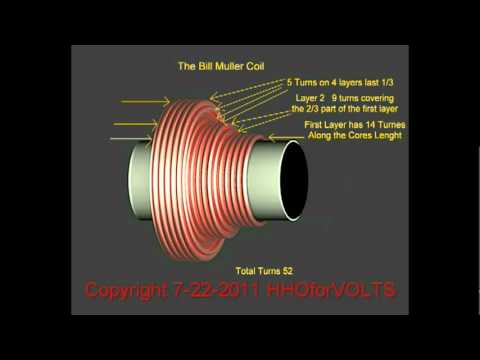
    One thing I observed is that it appears his coils are somewhat cone shaped and I believe there may be a specific reason for winding less wire close to the magnet.
    This design reminds me of the original Muller Motor coils.


    I do have the Kromrey DVD (along with many others from the series) but it's been a few years since I viewed it so I do need to review that.

    Not sure about Barium Ferrite magnets.
    As near as I can tell; this actually is the same thing as the common ceramic magnets as described here-


    And the photo of John's original converter looks like he used the same 1.875" x 0.875" x 0.375" ceramic-ferrite magnets commonly used in many SSG projects.

    Am I missing something here?
    Aren't ceramic ferrite magnets the same as BaFE magnets?

    And if not, can you provide a reference or source?

    I do have brass shaft and a few different types of slip rings.
    I also just acquired a very nice 3", 3lb brass disk and hope my drill press and skills are good enough to make a decent flywheel somewhere close to being true and balanced...

    Thank you for your assistance.

    Kindest regards;

    }:>
    Yes! i guess Ceramic magnets #8 often refered by JB himself..are indeed Bafe based!!!
    Rgds,
    Faraday88.

    Leave a comment:


  • Scorch
    replied
    Ah; there he is! Hey Aaron.

    I sent private messages through this forum to you on 8/30 (subject: "Kromrey Disclosure"), on 9/19 (subject: "Kromrey Disclosure" [resend]) and on 9/25 (subject: "are you still there?"). (see my sent items directory in my message center)

    If they never got to you then no worries. Probably just a site glitch although they are still there in my "sent" items...

    If there is any additional information about John's original Kromrey Converter; this would be very useful.
    Even just a couple really good high resolution photos would be a very nice addition to this thread.

    Tom has already revealed that a goal appears to be coils wound with 3 lengths of 23 AWG to be around 3.1 ohms and this in itself is very useful.
    I do have the energy from the vacuum DVD on this but still need to review that since seeing it a few years ago.

    Thank you for all your help.

    Kindest regards;

    }:>


    Originally posted by Aaron Murakami View Post
    What messages?

    Leave a comment:


  • Aaron Murakami
    replied
    Originally posted by Scorch View Post
    And this is not first time this has happened and also Aaron hasn't replied to the last three messages over the last few weeks and don't know why. . .
    What messages?

    Leave a comment:


  • Scorch
    replied
    Hey Tom.

    Fourth try is a charm? I am not sure but I think there is a web form bug because it appears this site has crashed several times after I tried to reply and I have to keep 'tweaking' things to get this to work...
    And this is not first time this has happened and also Aaron hasn't replied to the last three messages over the last few weeks and don't know why. . .

    At any rate; thank you for the pointers.

    I think I do have some 23 gauge on hand.
    Do I understand correctly that John actually wound three lengths in parallel for each coil?

    One thing I observed is that it appears his coils are somewhat cone shaped and I believe there may be a specific reason for winding less wire close to the magnet.
    This design reminds me of the original Muller Motor coils.


    I do have the Kromrey DVD (along with many others from the series) but it's been a few years since I viewed it so I do need to review that.

    Not sure about Barium Ferrite magnets.
    As near as I can tell; this actually is the same thing as the common ceramic magnets as described here-


    And the photo of John's original converter looks like he used the same 1.875" x 0.875" x 0.375" ceramic-ferrite magnets commonly used in many SSG projects.

    Am I missing something here?
    Aren't ceramic ferrite magnets the same as BaFE magnets?

    And if not, can you provide a reference or source?

    I do have brass shaft and a few different types of slip rings.
    I also just acquired a very nice 3", 3lb brass disk and hope my drill press and skills are good enough to make a decent flywheel somewhere close to being true and balanced...

    Thank you for your assistance.

    Kindest regards;

    }:>


    Originally posted by Tom C View Post
    Scorch

    1- 23 gauge will work.
    2 its not about turns, 3 strands in parallel to make a 3.1 ohm resistance circuit.
    3 - solid cores not laminate. use ductile iron, non ferrous axle, brass is preffered
    4- BaFE magnets are needed not ceramic or neo magnets
    5- a slip ring assembly and brushes from an alternator will work to get the power out of the rotor.

    .002 gap rotor to pole pieces. rotor gap radiused to match the pole piece.

    you really need the kromrey DVD


    Tom C

    Leave a comment:


  • Tom C
    replied
    Scorch

    1- 23 gauge will work.
    2 its not about turns, 3 strands in parallel to make a 3.1 ohm resistance circuit.
    3 - solid cores not laminate. use ductile iron, non ferrous axle, brass is preffered
    4- BaFE magnets are needed not ceramic or neo magnets
    5- a slip ring assembly and brushes from an alternator will work to get the power out of the rotor.

    .002 gap rotor to pole pieces. rotor gap radiused to match the pole piece.

    you really need the kromrey DVD


    Tom C

    Leave a comment:

Working...
X