Originally posted by John_Koorn
View Post
This relates to "deep cycle" flooded lead acid batteries - at least until you understand the process. I'd suggest that if after you follow the guide below your battery charge/discharge curve doesn't look like these, there is something wrong with either your battery or charger. Now, if you don't have the equipment that will chart for you, you can take a not of the battery voltage every 20 minutes or so and plug the Volts and Hours into a chart manually or Excel or similar..
Firstly, the charge curve.
Don't take too much notice of the "Volts" or "Hours on Charge" - it will be different depending on your charger and your battery and what condition it's in. What's important in this image is the M, N, O, P and R stages.
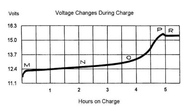
You want to continue to charge your battery past the "P" stage, as this is where most of the de-sulphation occurs. You'll know when to stop charging when the "P" stage is completed and you're in the "R" stage. I usually go for no more than about 20 minutes in the "R" stage. Anything more is a waste of time and energy and is not good for the battery.
See that little dip in voltage when you go from "P" to "R"? That's the impedance dropping in the battery, which is also a good indication that the battery is fully charged and also fully de-sulphated. However, in my experience that drop is only visible for a very healthy battery. Usually the curve will flatten out at the "P" to "R" stage. Don't wait forever for it to drop or as an indication the battery hasn't completed charging yet.
One piece of advice - if your battery is taking longer than 24 hours to reach the "R" stage your charger isn't powerful enough (or battery too large) and you won't see the capacity gains you should expect from a Bedini SG. Conversely, if your'e reaching the "R" stage in under about 12 hours you're charger is to too powerful (or battery too small).
Discharge curve -
Again, the "Volts" and "Hours" are subjective depending on the condition of your battery and the discharge rate. (The above chart is showing voltage/cell) The first thing to note is what the "Discharge Termination Point" should be. On a healthy battery I go as low as where the line on the charge starts dropping off quickly - this would be somewhere around the "1.9V" & "6.5" hours points on the chart. For a battery I am restoring, the Discharge Termination Point would be around the "1.95V" mark on the chart. I'll stress again that don't go by the voltage or hours, go by where the battery is on the discharge curve.
As for the discharge rate, for a healthy battery (by healthy I mean at least 80% of the Ah rating at the C20 rate) I would not discharge any more than C10 or you'll be killing the battery. Anything up to C50 is OK, or even C100 periodically is fine.
More importantly is to re-charge the battery as soon as possible after discharging. Think of it as every day you leave the battery discharged is another charge/discharge cycle you'll need to do to repair the damage - which done properly will take 2 days. So if you let a battery sit discharged for a month, it will take 2 months to restore it. If you're not going to use it, it's better to re-charge it straight away and top it off every 1-2 weeks to keep it healthy.
John K.
Firstly, the charge curve.
Don't take too much notice of the "Volts" or "Hours on Charge" - it will be different depending on your charger and your battery and what condition it's in. What's important in this image is the M, N, O, P and R stages.
You want to continue to charge your battery past the "P" stage, as this is where most of the de-sulphation occurs. You'll know when to stop charging when the "P" stage is completed and you're in the "R" stage. I usually go for no more than about 20 minutes in the "R" stage. Anything more is a waste of time and energy and is not good for the battery.
See that little dip in voltage when you go from "P" to "R"? That's the impedance dropping in the battery, which is also a good indication that the battery is fully charged and also fully de-sulphated. However, in my experience that drop is only visible for a very healthy battery. Usually the curve will flatten out at the "P" to "R" stage. Don't wait forever for it to drop or as an indication the battery hasn't completed charging yet.
One piece of advice - if your battery is taking longer than 24 hours to reach the "R" stage your charger isn't powerful enough (or battery too large) and you won't see the capacity gains you should expect from a Bedini SG. Conversely, if your'e reaching the "R" stage in under about 12 hours you're charger is to too powerful (or battery too small).
Discharge curve -
Again, the "Volts" and "Hours" are subjective depending on the condition of your battery and the discharge rate. (The above chart is showing voltage/cell) The first thing to note is what the "Discharge Termination Point" should be. On a healthy battery I go as low as where the line on the charge starts dropping off quickly - this would be somewhere around the "1.9V" & "6.5" hours points on the chart. For a battery I am restoring, the Discharge Termination Point would be around the "1.95V" mark on the chart. I'll stress again that don't go by the voltage or hours, go by where the battery is on the discharge curve.
As for the discharge rate, for a healthy battery (by healthy I mean at least 80% of the Ah rating at the C20 rate) I would not discharge any more than C10 or you'll be killing the battery. Anything up to C50 is OK, or even C100 periodically is fine.
More importantly is to re-charge the battery as soon as possible after discharging. Think of it as every day you leave the battery discharged is another charge/discharge cycle you'll need to do to repair the damage - which done properly will take 2 days. So if you let a battery sit discharged for a month, it will take 2 months to restore it. If you're not going to use it, it's better to re-charge it straight away and top it off every 1-2 weeks to keep it healthy.
John K.

just a question though, why is the discharge curve explained only for a single cell (2.2 v )? any thing in specific?
Best Regards,
Faraday88.

Leave a comment: