Announcement

Collapse
No announcement yet.

Branch's SSG Build

Collapse
X
 
  • Filter
  • Time
  • Show
Clear All
new posts

  • A multimeter is actually not that far off - the proof would always be to measure the output of a primary using 3amps (or whatever) to the SSG over a period of time, calculate the joules out and use the graph to monitor your drain.

    Charge it back up, then do the same thing using a resistive load of the same value...

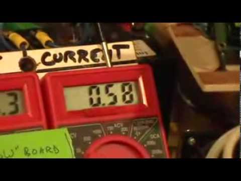
    TinselKoala shows a down and dirty quick way to see how far off your multimeter is in averaging the spike draw from the primary:
    Comment


    • Jelloir, thanks for the vid man! Your setup looks great, and I appreciate all the info shared!

      Originally posted by jelloir View Post
      Hi Branch, was about to type a post and figured a vid would be better. Hope it helps.

      Comment


      • John K- I am running a charge curve on one of these batteries I have that is taking a full charge from my solar panels. It's on the SG now rising slowly...it's at 13.71V now and still rising. Pulling 2A at 12V. It's probably gonna take a day or two to complete I'm guessing. But we shall see where it tops off at and if it's possible with a single coil at 12V to charge it fully.

        Originally posted by John_Koorn View Post
        jelloir, great video. You might want to try 470 ohm base resistors and a lower master base resistor - maybe about 10 ohms. But yes, you can see my point about over-saturating the coil and it heating up a little as a result. The machine will do this at higher input voltages. Will be interesting to see your rejuvenation results after a few runs.

        Branch, the only way you're going to be able to see if you're going to be able to charge those big batteries is to try. You're not going to be able to figure that out by attempting to calculate it as it it's pulsed DC - almost impossible to do accurately without very expensive equipment. The question is, is the battery being fully charged?

        As jelloir shows on his video, the TeslagenX 8 transistor SG board can run at 24v no problems. I've taken it higher, because we have to test everything we make and push it to the limits before we start selling it. Just make sure you don't accidentally disconnect the charge battery when doing this or the transistors will catch on fire. It's a pain matching up 8 transistors again

        John K.

        Comment


        • Patrick-

          Interesting, and thanks for sharing. Yeah I don't want to get too sidetracked just yet...trying to stay focused on one thing at a time.

          Originally posted by min2oly View Post
          A multimeter is actually not that far off - the proof would always be to measure the output of a primary using 3amps (or whatever) to the SSG over a period of time, calculate the joules out and use the graph to monitor your drain.

          Charge it back up, then do the same thing using a resistive load of the same value...

          TinselKoala shows a down and dirty quick way to see how far off your multimeter is in averaging the spike draw from the primary:

          Comment


          • I took one of my 150AH batteries that takes a good straight DC charge, and charged it all the way up on the solar tracker. I let it rest all day and it was sitting at 12.8V. I put it on my SG as the charge battery, to see if I could top it off with mode 1 at 12V. I could not. Highest I could get it was 14.18V while pulling 3A from a fully charged primary. I didn't want to push any more current as my coil started to get hot.

            I am trying the comparator now with the same setup, but only pulling 1.5A from the primary (which gives me my max RPM). This chart has been running about 22 hours, so you can see it is going VERY slow.

            I'll post another update when it's finished...could be a week though haha. Here's a link to the photo...as photo uploading seems to be broken at the moment.

            https://drive.google.com/file/d/0Bzs...ew?usp=sharing

            Comment


            • Hey Branch, I replaced the base resistors on my 8 Transistor

              So increasing the base resistance for 24V definitely helps as per John K. I decided to take it to the limit's of what JB suggests by using 680Ω base resistors and for 24V this seems about perfect.

              I may try similar on my 7 transistor rig but well see.

              Later,

              James
              Last edited by jelloir; 04-08-2015, 03:56 PM.

              Comment


              • Anyone have any experience with using a scope to align the coils on a multicoil machine? I have a 2 channel scope, and have mounted a 2nd coil roughly where it needs to be...but would like to dial it in. Any tips?

                Comment


                • Some video to share:

                  Comment


                  • Hey Branch,

                    Thanks for posting the video. Looks like it's coming along nicely.

                    At a guess the vibration sounds like a loose or partly loose welding rod in that coil. You could try stuffing another rod in there or just pouring some more super glue in there.

                    On the question about the coil spacing. Firstly, when you think about it, both coils should be firing at exactly the same time because they are sharing a common trigger winding. This is regardless of if they are spaced apart correctly or not. So theoretically if you overlay the scope traces over the top of each other they should line up perfectly. But they don't always, right? Why?

                    They don't because not all of the components are exactly the same. Yes, the transistors are matched but are all of the other components as well? Are all of the base resistors within 1 milliohm of each other? Are all of the diodes matched? etc. etc. You'll find the same thing even with a single coil. Unless every transistor is firing at exactly the same time there will be differences between the scope traces.

                    The difference should not be attributable to the coil spacing around the wheel. The real reason why you want to space the coils correctly is when the transistors all fire you want the magnet on the wheel to be in the best position possible that will give you the most rotational force. Also the same for when the transistors all switch off. If the coil spacing is a little off then it will only impact the efficiency of the machine.

                    Obviously what will also impact the efficiency is the magnet to coil gap and how evenly spaced the magnets are around the wheel.

                    So getting to back to your original question on how do you actually space the coil out? Well, the method I use is to first of all draw a line down the center of the side of one magnet. Then I also draw a line down the center of the main coil (through the middle of the core). At rest and without the second coil mounted both lines should match up. i.e. the center of the magnet lines up with the center of the core. This is your reference point

                    Now mount the second coil and set the appropriate gap. Adjust the second coil left or right. You will notice that if the second coil is not centered with the magnet on the wheel the lines that you drew for the main coil and its magnet (your reference point) will no longer line up. So you need to adjust the position of the second coil so that your reference point stays aligned.
                    You also need to make sure the the coils are also mounted exactly perpendicular to the magnet on the wheel. If not, you'll also notice that the wheel wants to run faster in one direction than in the other direction.

                    Hope this helps...

                    John K.

                    Comment


                    • if you were able to get to 1spike with 1 coil then it can be done with 2..... its a matter of the wheel not being able to accelerate. now that you know both boards are firing, work on spacing. John K is right about the common trigger..... did not even think about that.... it is now about getting the two coils to be in resonance with each other so the attraction of each magnet to the coil core is additive.

                      Tom C
                      Last edited by Tom C; 05-12-2015, 07:49 AM.


                      experimental Kits, chargers and solar trackers

                      Comment


                      • Comment


                        • Thanks everyone for the tips! I shot another video showing some progress and also what I'm seeing on my scope with both c

                          Comment


                          • Originally posted by Branch Gordon View Post
                            Thanks everyone for the tips! I shot another video showing some progress and also what I'm seeing on my scope with both c
                            Branch, does the wave form move at all if you move the coil? NOT the spike, the spike and the transistor ON will stay in the same place just like John K described. The WAVE should move if you move the coil unless you have something set on your scope to keep them lined up. The waves should look identical if you leave the energizer turned OFF. Did you ever do this and spin the wheel by hand?

                            Also, how confident are you that the magnets are evenly spaced? The wave is dancing around quite a bit...

                            I'm of the mind that all this is not as important as many tout. That's just me, I'm on my own planet This is almost exactly how John Bedini's 10 coil scope behaves. Nice Work BTW that's a clean build you have there! I would love it if you did a few runs just like this before making everything line up perfectly. Then see if there is any difference...

                            The reason the spike and ringing look different in each coil is because one of the coils has a trigger wire and one does not :-)
                            Cheers,
                            Patrick A.

                            Comment


                            • Hey Branch,
                              This is what I'm talking about:

                              Comment


                              • Thanks Patrick, I had not thought of using the scope to line up the coils that way. Amazing how we come up with different ways of doing the same thing.

                                Branch, as Patrick also eluded to - doesn't matter how well you line up the coils if the magnets spacing is not spot on. And then there's the variable gauss between all the magnets to throw in another variable.

                                Honestly, I'm of the same mind as Patrick - I don't think it's that critical to get it absolutely perfect. I think you have it just about where you want it. 2.2A is what I'd expect for what you have running.

                                What's the amp hour rating of that battery? (sorry if I missed it). I'm gonna throw it out there that if it's more than about 44Ah, you're not going to be able to fully charge it up to 15.8v

                                I'd be moving on to getting that 3rd coil running.

                                John K.

                                Comment

                                Working...
                                X