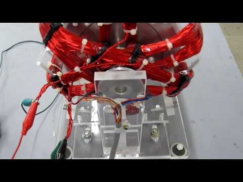
Hello either John. Can I sight an example? I have recently built a stator motor which is possibly a more sophisticated version of the fan motor project. The stator is more like 3" diameter and 12 legs. I am currently running the motor with one trigger and two power coils. I use the half wave circuit. As a mater of fact I'm using the little transistors as talked about a few times here. I have the extra power coil connected to a FWBR. I can run at 12 volts and between 120-150 ma. The charge circuit is very surprising considering the little transistors. I can easily charge a 330 volt 120 uF photo flash cap to 40-50 volts in less than a second. The cap discharge is a good whack with a nice blue spark. Last night and this morning I tried some charging tests with 7 ah motor cycle batteries. Surprisingly the charge looked pretty good. Now the question: If I would have had another identical power coil or two or three more could I charge a battery on each of them? This would seam to meet the description above. If L1 and L2 are running the motor and coil L3 was a good charger would L4 and L5 be equally as well? If so that would be great but here's the other thing: Would the load on the input go up with every battery connected? Would 2 for 1 actually mean you have more potential available from the two or three charged batteries than you had available from the run battery? Sorry John K, you've heard this before from me so this will be the last time I mention it here.
PS. This is all together different than using nodes right? Oh and one other question: Even though I'm having some promising charge characteristics, I'm probably not conditioning the batteries with this type of motor and circuit right? The scope does show some spike activity though.
John Hav
Added as an edit: I've been driving and am slightly out of town but thinking about what I said above makes me think I shouldn't have asked the questions but just wound another stator and try what I'm talking about. I won't be able to test further till Monday but I remember a temporary jump in current draw when connecting the capacitor. I don't think this happened when I connected the battery, as a matter of fact after running for a while the run battery starts to climb. how far that will go I don't know I'm sure it won't return to a starting rest voltage. I think the tuning changes as the charge battery starts to go up in voltage When I get home I should post a video for us to look at, if you're interested. I'd like an opinion as to whether the characteristics look like something worth pursuing or may not be what would be expected from the half wave circuit. Oh and I might have the answer already from John when it comes to the 2 for 1. Maybe right? It might depend oh how well you can match the impedance of a Class B amplifier circuit. That brings up a thought: To get another power coil on the stator the winding ratio would have to come down in order to fit. the 480 turns would drop to a little less but the coil resistance would be less than 2 ohms also which would probably match the impedance of the battery a little better No?
Take care all, have a good rest of the weekend.
John Hav.
-
Yes Ren, I have seen this video, I've watched it many times. This is probably the nicest build I've ever seen. I'm envious. I haven't made a three coil like this one. There's something else I have in my head and just can't shake it:
Free energy window motor
Here John shows a self running window motor, unless I'm mistaken. The build is only slightly bigger than my little one, the circuit seams to be a simple half wave. In the video John states that he can disconnect the battery and the motor will continue to run while the capacitor will continue to rise as was the input battery. This is different from self running until the capacitor runs down. This to me is the clearest and simplest demonstration of over unity and self running that I have seen so far and it doesn't look like it requires anything that most of can't make. Knowing the right materials the circuit, and how to tune the system would appear to be the question. There doesn't seem to be any cap pulsing. This is something we should be able to do. This is also the last time I'll reference this video and make that assumption here.
Thanks for reminding me about the Video Ren. I can watch it over and over.
John Hav.Leave a comment:
-
It is, I believe he referred to it as the baseball stitch coil?
@ JohnHav, have you ever built a three coil window, like the one in Johns video below? If I remember correctly some of Johns lab notes on the window motor specified that steel/iron could be used in the rotor, not shielding the magnets. A non magnetic shaft was used, and the "core" of the rotor is sometimes marked void/epoxy. I have noted John build window/energizers where the rotor appears to be non magnetic, the plastic bike wheel for example. The high speed window motor as seen below doesnt use steel/iron in the rotor design.
RegardsLeave a comment:
-
Leave a comment:
-
I see John, So the elimination of the 220 ohm resistor isn't necessarily a bad thing if you have the voltage adjustments down low enough to not overdrive the power transistors? Well I guess that means when I'm going up in voltage on the little circuits and starting to draw too much current it could be that I need that resistor. Thanks now that make sense. Should have been able to figure that out myself. I never was a fan of the outside coil but had luck with it on the little notch rotor in the mag lev base. Since we have mentioned coils do you mind letting us know what you think of the S shaped coil that goes around the outside but surrounds the entire rotor? Tis is all one single winding and goes across the N then over to the S and back the other way etc. until it goes all around the outside and has wires aligned with all six magnets.
Thanks John
John HavLeave a comment:
-
Window Motor Help
DadHav, Patrick,
That 220 ohm resistor sets the current for the Bi-Polar switch, and yes the Ferris Wheel is not much different. You can trigger the bi-polar switch either way, however it is possible to move the trigger coil away from the main windings. That way you can get perfect adjustments. If you change that 220 resistor the current through the switch will change and start to over heat the output transistors if you go the wrong way, if you have that problem you must balance the drive current with that resistor.
The P device is on the positive side and the N device is on the negative side so they are off until the switch occurs, coils then will float between output collectors and with the Bi-Polar switch it is then in bridge mode for north and south switching. Attached is what Rick did to the window motor and that is not correct even if it works, so it changed to what Carl Hurst did, Carl had a purpose for doing that. It's bad when things are just copied and the understanding is not there. If you understand that the motors and oscillators are just amplifiers, some mechanical and others solid state. The window motor is designed to run inside loops not on the outside. One could look at this like they make meters movements. The Newman Motor could be called the same thing if it did not have a commutator and the coil was reduced in size to focus the electromagnetic fields so it looked as if the rotor is passing through a windowpane.
But what Carl Hurst did does not represent the window motor as the fields work much different, and I understand why it was done. Here again copying without understanding the machine and no questions asked on Ricks part. They were trying to build a Zero Force motor here which works like an electrical turbine, which I have never shown. Peter L did build a beautiful machine that works properly and is very fast easily makes 10,000 Rpm's coasting, and that does use Neo magnets and generates no power in back EMF, so no drag and no Lenz's law applies here . so here is a link to a Zero force Motor http://rapidlibrary.com/files/john-b...ecbmi89on.html
John BAttached FilesLeave a comment:
-
-
John B. and all,
This is fantastic guidance. Thank you so much for this forum.
so my thinking was backwards. The real "purpose" for the EB resistors are to control the close - turn off the transistors.
So then, what is the purpose for the 220 ohm?
Thanks again - kind regards,
Patrick
PS - my interest at this point is because this same switch is being used for the Ferris Wheel - which my 6 foot wheel is currently spinning in our living room :-) So if you don't mind, if there are any differences in these fine points (i.e. resistors), it would be awesome to mention it.Leave a comment:
-
Hello John, John K and all.
I would be happy to draw out the circuit. However, I'm using your full wave on the first video. I think on that board I had a trimmer in the 220 ohm place as well as the normal trim pot. Also a switch to return the bridge to the input or send it out the connector on the side of the board. The circuits in the second video are slightly different because I jack up the normal output from collectors by adding the extra trigger or power coil in series with the collector voltage . I'm sure this is nothing new because I've never had a comment on it when I've mentioned it. John I would have included the circuits in my videos but I've never tried to ask you for permission. I was never sure of how you felt about my work because I don't usually mention the words Free Energy, Vacuum, Aether, Self Run. Etc. Ha, I've had to turn off comments on one video that .5 of the 1.3 million viewers where beating the crap out of me because I said High Voltage Without Power Supply. Ha, ha, I'll bet I don't have to tell you how that feels.
I have two coils that I use on the little window motor. The one with the long capacitor runs is 12 ohms power and 80 ohms triggers maybe 480 turns. The other is 5.8 ohms triggers and power coil. This one might be 250 turns or something like that.The rotor is neo magnets in mild steel about two pounds, non magnetic stainless shaft, ceramic bearings in stainless race. Yes with the half wave circuit made from the small transistors I can run for a few days on a 20F 2.7 volt cap. Ya, I know it's small but a big cap right? After a few days the cap will drop a volt and you have to adjust trim to run the cap down further. This may be a surprise but it's not unusual to start off with a 10 meg resistor for trim. Incidentally, you mentioned the resistor to make sure the transistor turns off. On some of my very lowest current runs I have noticed that I had a small current draw. 10 uA that I couldn't account for even when the rotor stopped. Now I know. John, I have always thought my motors where just build with exceptional free spin and balance, high turns ratio and just very efficient, and that's why I was able to run at low voltage and current. On the second video it just seems like 3 pounds of rotors a near double voltage and an LED is just a little more than should be expected from 5 ft. of mag ribbon around a small copper pipe. If you cared to make suggestions on the window motor I'd be happy to rebuild or make another one. I always wondered about the neo magnets but I've heard your recent comments about using ceramic. I have a steel rotor but don't know if that is the optimal choice. Also my builds are small and I know that is an issue also. Oh man, You guys got me started talking now. I'm sure your not even with me anymore but I did want to mention, I understand the importance of impedance matching and have to say I realize it's probably my greatest shortcoming with my experiments. I should have two power coils on my builds. On the window motors if I had a second power coil attached as I mentioned above to double the output and if it matched impedance of the battery there really might be something to talk about. I've just wound a 12 leg stator motor with two power coils and two triggers with intent to do exactly this. I lost one of the triggers with a wire break and had to run half wave rather than full wave. The isolated power coil seams to work very strong and should work well with a cap dump when added in series to the collector circuit the output is of course doubled. I could go on until everyone is begging for mercy, but I'll put something together to explain what was in the second video.
Take care guys. It's a pleasure to have this conversation.
John HavLeave a comment:
-
window motor help
John Hav.
Do you mind showing the circuit your using so others can see what is going on? Or if you prefer to keep that to yourself that is ok also. If I'm close the coil impedance is around 5 ohms, Cole circuits were 3.3 Ohms and some that I built were 10.2 ohms. The window motor on the Rense show was 5 ohms self running on the cap 40000Uf, for about 10 minutes. At the current your using it should run for a very long time. Happy to talk to you about the window motor, you do excellent work and very neat to say the least. Excellent circuit too. I have two extra windings on that motor I showed #20 and #21 wire as I was doing series hook-ups with short triggering.
John BLeave a comment:
-
John. Thank you, the compliment means a lot to me. I do remember some things about the difference between class AB and B also remember emitter resistors had something to do with distortion at crossover between the NPN and PNP. I just didn't make that association until you mentioned making sure the transistors turned off. I'll have to read up on that a little bit to freshen my memory. I think I'm getting the the point you're making. Thanks I'll change my mind a little about what I'm doing.
Thanks again
John HavLeave a comment:
-
R-Charge does not know my work
DadHav,
The 470 Ohm resistors are in the circuit to make sure the base emitter circuit turn off. The circuit was taken from a full Complementary Symmetry Amplifier Ron and I built ( Class B) . You always drive the load in this circuit from the collectors, because of the impedance of the coils. however for power you must build the circuit using Darlington on the PNP side and the NPN side. The full wave bridge is directly across the collectors of the N and The P device, or the Coil. The circuit is arranged to isolate the power supply BEMF is routed to the capacitor and then returned to the battery, for extended run time. If you charge the capacitor and pulse the primary battery the motor must be completely off and then Joules are important stored in the capacitor but you must be at double the battery voltage for the pulse dis-charge to either the primary battery or the secondary battery. You must look at this circuit as an amplifier . People for some reason do not see this, the same applies with the SG circuit. The coil in the circuit is an impedance and it must be calculated that way in terms of gain to the circuits, and that gain is applied to the battery, impedance wise. I think people are missing the point of what the circuit really is, if you wind 3 coils together on the same form, they are all independent charging circuits, think about what I just said here.
The BEMF is much lower then the battery voltage, so the spike is charging the cap in time, so time charging. I do know your work and it is excellent, AAA+John BediniLeave a comment:
-
Hello Ren, I haven't looked at that video in a long time but when I did I saw a link on it to an update where I took the motor apart to show how it was made but I did have a 5 diget meter reading with the little transistors and no resistors except trim. I think the most I ever ran with so little was on the video Window Motor Runs Window Motor. I used all little transistors with bipolar circuits and no resistors other than trim. I took the output from a notch rotor WM and doubled the voltage by adding the spare trigger coil in series with the power coil. Then I ran the second larger WM at almost twice the voltage. I took the output from the second WM and ran an LED from it. All this was from what I learned from John B, and to top it off I was running everything from a single copper magnesium cell that I learned from John's early crystal battery research. I'm not here to showcase my videos but if you are interested in luck I've had with the little transistors then this would be the video to watch:
Window Motor Runs Window Motor. - YouTube
I often look back at this video and wonder why I didn't persue this further. I almost don't believe it myself. I must have accidentally come close to getting what John has been trying to explain.
John Hav. I see there's another John H. on the forum so I'll use the first letters of my last name now.Leave a comment:
-
Just for reference here is some of Dadhavs work.Originally posted by DadHav View Post
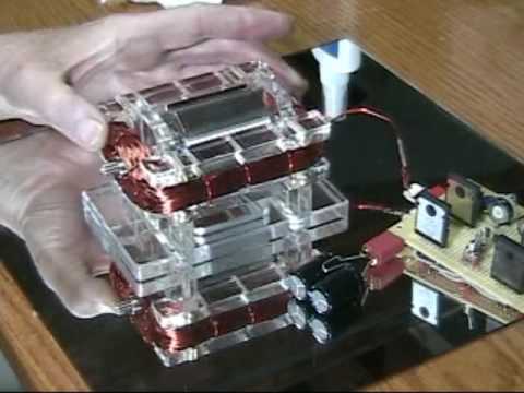
Dadhav, you used to have another video of it running on next to nothing, you were measuring the voltage on the cap to 4 or 5 decimal places before you could see the fluctuations if I remember correctly. Was that the 1/2 circuit you refer to above (MPS/2n2222 combo) that had no resistors except in the trigger? EDIT: I found it, its "Window motor assembly.."
RegardsLast edited by Ren; 08-08-2012, 03:39 PM.Leave a comment:

Leave a comment: