Announcement

Collapse
No announcement yet.

R-Charge Window Motor

Collapse
X
 
  • Filter
  • Time
  • Show
Clear All
new posts

  • min2oly
    replied
    Originally posted by min2oly View Post
    John B.,
    Thank you for sharing this version of the Zero force build. It never occurred to me to use the toroid - now that I see it, I can see that it was in plain sight.
    Is that a soft iron toroid?
    is the toroid a complete circle, or is it broken with a slight gap?
    what gauge, ohms is the wire?
    I finally have some matched mjls for the full bipolar switch, I'll be trying them out with our various builds and very much want to replicate the zero force as well. Thank you for personally taking the time on this forum and for sharing so much. I might be slow as a turtle, with my mind on a goal, I never give up.
    Kind regards ,
    Patrick

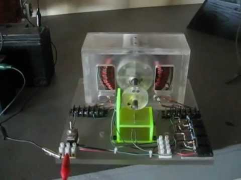
    I was recently re-watching DVD 2 for the umpteenth time and noticed this zero force toroid build sitting right on the table. Tom Bearden mentioned JB has at least a hundred different builds laying around. Amazing amount of research.
    Patrick

    Leave a comment:


  • DadHav
    replied
    Originally posted by John_Bedini View Post
    DadHav,
    The 470 Ohm resistors are in the circuit to make sure the base emitter circuit turn off. The circuit was taken from a full Complementary Symmetry Amplifier Ron and I built ( Class B) . You always drive the load in this circuit from the collectors, because of the impedance of the coils. however for power you must build the circuit using Darlington on the PNP side and the NPN side. The full wave bridge is directly across the collectors of the N and The P device, or the Coil. The circuit is arranged to isolate the power supply BEMF is routed to the capacitor and then returned to the battery, for extended run time. If you charge the capacitor and pulse the primary battery the motor must be completely off and then Joules are important stored in the capacitor but you must be at double the battery voltage for the pulse dis-charge to either the primary battery or the secondary battery. You must look at this circuit as an amplifier . People for some reason do not see this, the same applies with the SG circuit. The coil in the circuit is an impedance and it must be calculated that way in terms of gain to the circuits, and that gain is applied to the battery, impedance wise. I think people are missing the point of what the circuit really is, if you wind 3 coils together on the same form, they are all independent charging circuits, think about what I just said here.
    The BEMF is much lower then the battery voltage, so the spike is charging the cap in time, so time charging. I do know your work and it is excellent, AAA+John Bedini
    I have a generator coil on a stator motor that can run small loads without the mechanical oscillator changing speed or the input current going down. In the video there is the little alum battery running the stator motor. It's running at about 165 ma. The bulb is incandescent and draws about 75 milliamp. When I add the bulb parallel to the input battery the current draw goes up over 200 ma, but when I put the bulb on the output (generator coil & FWBR) the current drops from the 165 ma to about 135 or something like that. The motor RPM stays the same and the current transition shows up on the battery as it recovers accordingly. OK so I'm thinking if one coil runs a load and decreases the amount of current then, two should be better right? Anyway see what you think. Maybe Carl will like this also, he likes all the different kinds of motors.
    Free Energyy From Generator Coil - YouTube
    Hope you enjoy the short clip. I took it out of the hour long video I ended up with but haven't posted.
    Take care all
    John Hav
    Last edited by DadHav; 09-18-2012, 05:24 AM.

    Leave a comment:


  • Jeffrey Joseph
    replied
    Thanks evreyone for the diagram. I will go to DadHav u tube and take a look Thanks again Jeff

    Leave a comment:


  • Jeffrey Joseph
    replied
    Hello everyone
    I have two tiny motors. one is original with large mags, the other is modified with small neo mags all north. I want to use the original window motor as a motor and run the other as an energizer.
    Is there a diagram of an electronic circuit that will run this?
    I've been having sooo much fun with this stuff. I have a drill press in the living room. Do I need therapy?
    Thanks guys for all your help. Happiness and Joy from Jeffs porch in Hilo.

    Leave a comment:


  • min2oly
    replied
    Originally posted by John_Bedini View Post
    John Hav,
    The reeds in this motor do not limited the speed I was just coasting it, I will do another video at very high speed, I can run it at speeds that will burn the bearings up, I really do not want to do that to the motor. I will make a simple one to show how to do it. During the moving from one shop to another the first motors got destroyed.
    John B.,
    Thank you for sharing this version of the Zero force build. It never occurred to me to use the toroid - now that I see it, I can see that it was in plain sight.
    Is that a soft iron toroid?
    is the toroid a complete circle, or is it broken with a slight gap?
    what gauge, ohms is the wire?
    I finally have some matched mjls for the full bipolar switch, I'll be trying them out with our various builds and very much want to replicate the zero force as well. Thank you for personally taking the time on this forum and for sharing so much. I might be slow as a turtle, with my mind on a goal, I never give up.
    Kind regards ,
    Patrick

    Leave a comment:


  • DadHav
    replied
    Originally posted by SixtythreeXKE View Post
    Or what if someone were able to combine a G-field Kromrey device with an iron reluctance motor. When one looks closely, the Kromrey device is only a hair's breadth away from a reluctance motor already! My word, the mind reels at the possibilities... Cogs are spinning, bearings are smoking, gaskets are leaking, we're about to throw a rod...
    Carl Hurst
    My word, my mind is rockin and a-reelin. I think if someone had a phenomenal G-field or Kromrey the prime mover could be built right in so it's a one piece unit.
    John Hav
    Last edited by DadHav; 08-29-2012, 06:00 AM.

    Leave a comment:


  • DadHav
    replied
    Originally posted by SixtythreeXKE View Post
    Greetings, John:
    The trick is not to use reed switches, like some do, to turn on drive voltages (although you do get some nice sparks with concomitant radiant spikes). The trick is to use reeds to send only bare minimum turn-on voltage to power transistor bases. Thus you can use almost no current and very low voltage through the reeds, and they function much like Hall sensors this way, without using even the small power the Halls need. When a reed is open, you really have NO current drain at all. The reeds run fast and last a long time when used only for minimum turn-on voltages.


    Warmest regards
    Carl Hurst
    Hello Carl. Thank you for taking so much time and sharing your ideas. Yes, I feel the same respect for John but have to say at times I tend to be a slight burr under the saddle. Ya, know it's a shame you can't just record some of the comments so people can understand the demeanor associated with the comment. Yes, of course, I should have thought of the reeds as sort of a Darlington configuration or low current. Hey lets have some fun. You mentioned on-time with magnets. Lets see if John is reading this and has a lab note someplace. Sometime in the future I would like to make a window motor commutator with magnets and hall effect sensors. Pretty common but I want to put the magnets on two symmetrical disks that can be rotated. With a hall switch you can turn the pulse on with magnets on the front disk then turn it off with the magnets on the back disk. You could set any degree of on time that you would like. What would you call that? a Mechanical Pulse Width Modulated Commutator? Ha, I share your interest in running one motor with another. You can see this all over my videos. I have used my very efficient window motor to turn a stator motor which is almost zero cogging. The stator motor activates it's associated SSG circuit without having an input on the circuit. Just a capacitor in place of the input battery happens to charge and run the circuit. I was hoping I could get more radiant potential from the stator motor than what potential was required to run the window motor. I'm probably way off track and just provide a chuckle for those who really know what their doing but you can get an idea of what I was thinking of here if you haven't been on my channel.
    High Voltage Without DC Power Supply II - YouTube
    I think I share your view even though I'm not totally familiar with the Kromre or G Field. I've looked at drawings but never made one.
    Ya, sure, you betcha. A big, fast, efficient large diameter outrunner runningspinning a G-field would be plenty enough fun for a while.
    It's great to finally be able to talk with you and John. I'm really happy when I'm working on some kind of machine that hasn't bean made and tested already. I keep hoping someday to discover something that's not on the note pad someplace. Ha, lots of luck with that one right?
    Take care Carl and thanks for sharing the family comments. I can see where your heart is at. I hope we can talk more about these ideas. I'm not sure if we're on the right thread or even if we might be over stepping our boundaries, maybe someone will advise us.
    John Hav
    Last edited by DadHav; 08-29-2012, 05:55 AM.

    Leave a comment:


  • SixtythreeXKE
    replied
    Or what if someone were able to combine a G-field Kromrey device with an iron reluctance motor. When one looks closely, the Kromrey device is only a hair's breadth away from a reluctance motor already! My word, the mind reels at the possibilities... Cogs are spinning, bearings are smoking, gaskets are leaking, we're about to throw a rod...
    Carl Hurst
    Last edited by SixtythreeXKE; 08-26-2012, 05:35 AM.

    Leave a comment:


  • SixtythreeXKE
    replied
    John:
    I really do like your idea of using the stitch winding for a stator, then have an outside armature, like the magnet arrangment in most small engine magnetos and older motorcycle magnetos, where the magnets are attached to the inside diameter of a cup. Of course, if you want torque, go with a very large radius. Then you not only get the great efficiency of the A-field motor, but the added power from the moment arm from the diameter of the armature. As Lon Chaney said: "Ah, Very, very clever, no. 1 son." The wire notches must be pretty wide, as you want substantial bundles in there, with some appreciable "surface area" of parallel wires facing the magnets. You want a pretty good, dense curled flux field right on the surface of that stator at each notch. Then, if you REALLY want to zero out the Lenz effect, then you insert the magnets so that the sides of the magnets face inward, such that the magnets are in magnetic "series" (NSNSNSNS) around the inside of the armature, with appreciable gaps between, say at least three wire bundle widths. Then you not only get a strong repulsion from the primary North curl flux, but also an attraction to the upcoming magnet's south face. Yeeowza. No I want to build one...

    Warmest regards and thanks for sharing your great ideas!
    Carl Hurst

    Leave a comment:


  • SixtythreeXKE
    replied
    Greetings, John:
    The trick is not to use reed switches, like some do, to turn on drive voltages (although you do get some nice sparks with concomitant radiant spikes). The trick is to use reeds to send only bare minimum turn-on voltage to power transistor bases. Thus you can use almost no current and very low voltage through the reeds, and they function much like Hall sensors this way, without using even the small power the Halls need. When a reed is open, you really have NO current drain at all. The reeds run fast and last a long time when used only for minimum turn-on voltages.

    Warmest regards
    Carl Hurst

    Leave a comment:


  • SixtythreeXKE
    replied
    Dejavue all over again...

    Originally posted by DadHav View Post
    Thank you for the answer Carl. I think I understand what you where trying to accomplish. I spent a great deal of time trying to modify eddy currents in the popular R/C hobby motors. They're a challenge for sure. I was only partly successful. Carl you know it's a funny thing, I don't read nearly as much as I should, but I'm getting use to finding out that John B. has done most everything I think of, already. Does that make any sense? Well he's an amazing person.
    Thank you Carl
    John Hav
    As they say in Minnesota: "Ya, sure, you betcha. So you noticed that 'been there, done that' thing about Mr. John Bedini, then?" In almost every discussion I have ever had with that extraordinary man, the Tesla of our day (indeed, one of my twin daughters' middle name is Tesla, for obvious reasons), we have come across "new" ideas that he is able to find lab notes for, going back to at least the 80s. Yes, he has done it all. He knows exactly what each of us experimenters are talking about and can either pull a version that contains the idea right off his shelves, or throw one together in a matter of a couple of hours on his bench to prove a point. I love talking to the man, and once you get the hang of his communications, you get as much information between the lines as you do from the direct content. I have observed him simply nod and smile, because I either "got it" or was onto something he merely inferred. Let me tell you, there are few things in life as rewarding as a compliment or pat on the back from the likes of John Bedini. He has encouraged me over the years, he has corrected me, he has guided me, he has offered help to me, and I am always impressed because he knows exactly what I am talking about and gives both constructive criticism and useful guidance to help my projects come together with less hiccups. He knows every twist in the road and helps to avoid them, if we pay attention and listen carefully.

    As for the baseball stitch or S-cage stator A-field motors (the former for four, the latter for six magnets), yes, you can bifilar wind these. I have done it. But it did not suit my purposes for the following reasons:
    1. It causes a feedback loop which turns on the transistors, and thus creates the "spike comb" signal. It is not as good as that produced by Mr. Bedini's energizers. But I guess you could slowly charge secondary batteries with it.
    2. Because of the high freq spikes, it is not the best, most powerful pulse to drive the armature. For my purposes, you want a good, solid square ON pulse, the width of which may be determined by the width of triggering magnets passing your reeds or your Hall sensors. A tiny mag will produce a short pulse at low RPM, and a downright miniscule pulse at high RPM. (This is one thing I love about these A-field motors.)

    After experimenting with my 24inch diameter magneto (I am on hiatus right now, dedicating myself to my daughters' educations overseas), I shall endeavor to build a honker of a G-field energizer (also known as a Kromrey device), driven by an ultra-efficient zero force, zero Lenz A-field motor. As the G-field type magneto comes up to speed the cogging goes away. As the G-field is loaded with the right impedance, the mechanical load drops and the assembly (motor&generator) rise, and input drive current drops lower and lower.

    In my heart of hearts, I am certain that the amazing feats Mr. Bedini proved in his famous townhall conference in California can be improved upon by the use of such a super efficient zero force motor over a regular DC motor that he used. The effects, though envisioned in my dreams, boggle the mind. Now, if only someone could marry a Flynn motor or parallel flux path motor to a window or A-field motor. The geometry eludes me at present, but it does keep me awake some nights.

    Always a pleasure to correspond with like-minded experimenters, and your work is truly astounding in cleanliness and execution.

    Very best regards to you, blessings to the group, and salutes to Mr. Bedini, Grand Master of our Radiant & Magnetic Order! -

    Carl Hurst

    Leave a comment:


  • DadHav
    replied
    Originally posted by John_Bedini View Post
    John Hav,
    The reeds in this motor do not limited the speed I was just coasting it, I will do another video at very high speed, I can run it at speeds that will burn the bearings up, I really do not want to do that to the motor. I will make a simple one to show how to do it. During the moving from one shop to another the first motors got destroyed.
    Really John, I always thought, and I think most others also, that the reeds where limiting and wore out quickly. I'm sure everyone would like to see a video with a high speed rotor and reeds, but I don't want you to burn up your bearings. You saying so is good enough for me. I wonder if modern day reeds are better than my 40 year old ones
    Thanks John
    Take Care
    John Hav

    Leave a comment:


  • John_Bedini
    replied
    John Hav,
    The reeds in this motor do not limited the speed I was just coasting it, I will do another video at very high speed, I can run it at speeds that will burn the bearings up, I really do not want to do that to the motor. I will make a simple one to show how to do it. During the moving from one shop to another the first motors got destroyed.
    Last edited by John_Bedini; 08-25-2012, 09:32 AM. Reason: correction

    Leave a comment:


  • DadHav
    replied
    Originally posted by John_Bedini View Post
    In this Video I'm showing a "ZERO FORCE MOTOR" The motor works opposite the normal SG or DC motor. No Back EMF is developed in the motor, so it does not generate anything. The discussion will take place in the Energysciencefourm. here .http://www.energyscienceforum.com/ The motor was built by Peter Lindermann from one of my early models. The Forum is dictated to the people that worked so hard on the SG groups.
    Thanks for watchingJohn Bedini
    Hi John. Thanks for posting the video. Nice motor for sure. Fast indeed, and probably limited a little by the reed switches right. The only time I ever threw a magnet was using a coil something like this to drive the rotor. There's still a dent in the beam from where the magnet hit. Never did find the magnet. You know I'm a big fan of the outrunner motors. I keep thinking because this type motor is designed for torque that magnets running around the outside instead of the inside would really be powerful. Maybe to slow though, right?
    Thanks again, I'll have to read more about what you've already done with this. I'm itching to build something I guess. I've spent some time following one of the popular asymmetrical DC motor forums but I'm still reluctant to get into a serious build.
    Thanks John
    John Hav

    Leave a comment:


  • DadHav
    replied
    Originally posted by SixtythreeXKE View Post
    Hi, DadHav:
    The reason I always referred to the motors I built as A-Field motors is very specific. The A-Field was brought to our attention long ago, I think in the early 80's by Mr. Bedini. He and Tom Bearden referred to the A-Field, both N and S, in a hand drawn pencil drawing. It is the A-field that I have made use of in all my iterations and experiments. I was ever striving for a strong, pulsed no Lenz, no BEMF, minimum eddy current motor, with which to drive a very effective magneto at high speed using very little current. I have other iteration I did not video, including ones similar to the zero force motor Mr. Bedini showed in his WMV video recently, and also similar to the one that Dr. Lindeman built. That iteration showed some really peculiar characteristics. Let's just say that magnets like being sucked into the center of coils, so you need to time both energizing and also the collapse of coil field to get the most powerful attraction AND repulsion of armature magnets. Their orientation is also very interesting...

    Anyway, the A-field term was appropriate, as it is the curl field next to a wire bundle I am using, but NOT strictly in a "window" configuration. But the only venue we had at the time for posting these experiments was the Window Motor group, as that is the closest related thrust in motors and energizers. Here is the link to that old S-curved stator winding: S-Cage Stator and Reed Switch-Driven Bedini-Cole Commutator Large Window Motor

    The "baseball stitch" winding I used on a four pole armature....


    Hope that helps!
    Best regards
    Carl Hurst
    Thank you for the answer Carl. I think I understand what you where trying to accomplish. I spent a great deal of time trying to modify eddy currents in the popular R/C hobby motors. They're a challenge for sure. I was only partly successful. Carl you know it's a funny thing, I don't read nearly as much as I should, but I'm getting use to finding out that John B. has done most everything I think of, already. Does that make any sense? Well he's an amazing person.
    Thank you Carl
    John Hav

    Leave a comment:

Working...
X