 Tweet
Tweet
Originally posted by Catrinisin
View Post
I have that same SCR. The only thing I've added was an LED from cathode to zener to gate.
Still... when I've moved to larger setups w/ large battery banks - this one is too small and heats up and/or locks up.
Everyone should try it, it is very reliable w/ the right energizer and charge battery.
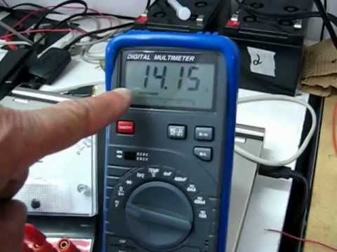
The drawing in my vid is wrong, but the close up of the actual SCR is easy to see and connected and operating correctly.
Chris has the correct drawing here.
-KR
Patrick


Comment