Announcement

Collapse
No announcement yet.

Two Stage Mechanical Oscillator Replication

Collapse
X
 
  • Filter
  • Time
  • Show
Clear All
new posts

  • Two Stage Mechanical Oscillator Replication

    Hi All,

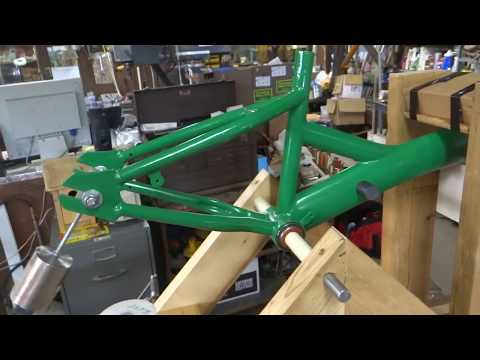
    I know there are already a couple of other threads on this, but decided to start a new one to discuss my 17 year old grandson's (Daniel) replication of Veljko Milkovic’s 2-stage mechanical oscillator (with a little help from grandpa). I gave him an old, small, girls bicycle which he cleaned up and painted. Then I helped him machine an adapter sleeve for two ball bearings to replace the pedal crank for the pivot point. He took all this home and constructed a nice wooden A-frame for a base and installed the bicycle frame in the base with a 5/8" rod through the pivot bearings and wooden A-frame.

    Next I helped him machine a stainless steel piece for a pendulum and an aluminum piece for a ball bearing pendulum pivot. These were attached together with some ready rod and then bolted into place at the rear wheel attachment location of the bicycle frame. He then added two upright supports for beam travel stops on the work (long) end of the bicycle frame near the front fork tube. And we added a small spring to assist the downward movement of the work end.

    I had an old, small SSG coil and single transistor circuit laying around, so we mounted these under the pendulum to which we added a ceramic magnet. We have it working and pounding away at the stops on the long end. But we need a little stronger coil and circuit to get full swing of the pendulum for maximum effect. So we wound a new coil with one trigger, two power, and one isolated recovery winding. Next week we will build a new, better SSG circuit with the recovery going back to the run battery for reduced primary current draw as shown by Aaron.

    The plan is to use the mechanical output to drive a flux gate generator for useful electrical output.

    Click image for larger version

Name:	sgrecoverycircuit.jpg
Views:	2
Size:	647.0 KB
ID:	51475


    Last edited by Gary Hammond; 04-13-2019, 03:14 PM. Reason: insert video

  • #2
    Outstanding! I've wanted to build something like that. Now make the pendulum go loop de loop!

    Comment


    • #3
      Great start! Is that SG circuit running in attraction or repulsion mode?
      Aaron Murakami


      You never change things by fighting the existing reality. To change something, build a new model that makes the existing model obsolete.” ― Richard Buckminster Fuller

      Comment


      • #4
        Thanks Guys,

        It runs in either attraction or repulsion mode about the same. But we are running in attraction mode to make it a little more efficient. The video was shot with the old coil and circuit. We have the new coil made and installed. We will be making the drive circuit for it today when my grandson comes over for shop class. He is doing the project with a little input from grandpa.

        I think this love of "rocking" all got started at his first Christmas back in 2002.


        Comment


        • #5
          Hi,

          My grandson got the drive circuit for the new coil about 2/3 done this afternoon. Here's a few pics of the afternoon in progress.

          Click image for larger version

Name:	DSC06969.jpg
Views:	1
Size:	989.1 KB
ID:	50168

          Click image for larger version

Name:	DSC06970.jpg
Views:	1
Size:	1.00 MB
ID:	50169

          Click image for larger version

Name:	DSC06972.jpg
Views:	1
Size:	993.5 KB
ID:	50170

          Click image for larger version

Name:	DSC06973.jpg
Views:	1
Size:	963.4 KB
ID:	50171

          Comment


          • #6
            Very cool to see a 17 year old getting involved!
            Aaron Murakami


            You never change things by fighting the existing reality. To change something, build a new model that makes the existing model obsolete.” ― Richard Buckminster Fuller

            Comment


            • #7
              Hi,

              Well, my grandson finished up the circuit this afternoon for the new coil we wound. We tried it out with double stacked magnets and it wouldn't keep running. So we went back to a single magnet and it still doesn't work like we had hoped for. It requires much stronger current pulses than the old coil, and doesn't trigger as well as the first circuit and coil did.

              The old coil had one #26 trigger winding and one #23 power winding each 275 feet long. The new coil has a #23 trigger winding, two #20 power windings, and another #20 recovery winding all 130 feet long. So the new coil has fewer total turns of the larger power wire which requires more current to get the same # of ampere turns of magnetic field strength to drive the pendulum. And with fewer turns of the trigger wire, the air gap between the coil and magnet has to be smaller and fails to trigger when the gap gets too large. The gap isn't always consistent as the work end goes up and down which causes it to stop triggering unless the base resistance is turned down to almost zero ohms.

              We were pleased, however, that the recovery coil system worked well at reducing the current draw from the battery. This whole device is very sensitive to every little change in either the mechanical side or the electrical side of the set up. So we are back to winding another new coil and maybe making some mechanical changes as well. This is all trial and error on our part and since it's my grandson's project nothing gets done on it unless he's here.

              P.S. Does anyone have a circuit that causes the coil to both attract the magnet on approach and then repulse the magnet as it leaves. I think someone on the forum developed a circuit like that maybe four or five years ago to power a bicycle wheel with?
              Last edited by Gary Hammond; 04-28-2019, 07:54 PM. Reason: add post script

              Comment


              • #8
                Originally posted by Gary Hammond View Post
                Hi,

                Well, my grandson finished up the circuit this afternoon for the new coil we wound. We tried it out with double stacked magnets and it wouldn't keep running. So we went back to a single magnet and it still doesn't work like we had hoped for. It requires much stronger current pulses than the old coil, and doesn't trigger as well as the first circuit and coil did.

                The old coil had one #26 trigger winding and one #23 power winding each 275 feet long. The new coil has a #23 trigger winding, two #20 power windings, and another #20 recovery winding all 130 feet long. So the new coil has fewer total turns of the larger power wire which requires more current to get the same # of ampere turns of magnetic field strength to drive the pendulum. And with fewer turns of the trigger wire, the air gap between the coil and magnet has to be smaller and fails to trigger when the gap gets too large. The gap isn't always consistent as the work end goes up and down which causes it to stop triggering unless the base resistance is turned down to almost zero ohms.

                We were pleased, however, that the recovery coil system worked well at reducing the current draw from the battery. This whole device is very sensitive to every little change in either the mechanical side or the electrical side of the set up. So we are back to winding another new coil and maybe making some mechanical changes as well. This is all trial and error on our part and since it's my grandson's project nothing gets done on it unless he's here.

                P.S. Does anyone have a circuit that causes the coil to both attract the magnet on approach and then repulse the magnet as it leaves. I think someone on the forum developed a circuit like that maybe four or five years ago to power a bicycle wheel with?
                Hi Garry,
                Great Going Sir! I adore at your Synchronicity/binding with your Grandson. Keep up the spirit. And of course your inclination towards build things at a age such as yours.
                Best Regards,
                Faraday88.
                'Wisdom comes from living out of the knowledge.'

                Comment


                • #9
                  Originally posted by Gary Hammond View Post
                  P.S. Does anyone have a circuit that causes the coil to both attract the magnet on approach and then repulse the magnet as it leaves. I think someone on the forum developed a circuit like that maybe four or five years ago to power a bicycle wheel with?
                  Can you use the Zero Force Motor circuit? It reverses polarity.

                  If you have the ZFM package - see Peter Lindemann's 2002 ZFM schematic. You need to switch MR1 and MR2 (magnetic reed) sequentially for an attraction then repulsion.

                  However, with a pendulum, it will come back in the opposite direction and you wouldn't want it to switch them in the opposite sequence or it will fight.

                  Anyway, you have to figure a way around that with some switching mechanism.
                  Aaron Murakami


                  You never change things by fighting the existing reality. To change something, build a new model that makes the existing model obsolete.” ― Richard Buckminster Fuller

                  Comment


                  • #10
                    HiAaron,

                    I found the thread I was partially remembering at http://www.energyscienceforum.com/sh...bigmotherwhale . I think with a little modification, this might do what I want.

                    Comment


                    • #11
                      wow, someone really butchered one of my Schematics. i'm not even sure what it's susposta do.....

                      edit:

                      after studying this. i see that they are trying to get the charging battery to drive the the 2nd transistor from a 2nd trigger coil.....

                      but this hookup will not work the way it is drawn.....
                      Last edited by RS_; 04-30-2019, 10:07 AM.

                      Comment


                      • #12
                        Hi RS,

                        Originally posted by RS_ View Post
                        wow, someone really butchered one of my Schematics. i'm not even sure what it's susposta do.....
                        I remembered when this was posted four or five years ago. I had to do a search to find it. I didn't realize he (bigmotherwhale) had used and butchered one of your schematics. It is supposed to flip the coil core from attraction to repulsion as the magnet passes giving it a double "kick". It uses separate windings on the coil to do this.

                        A better way (as suggested by Aaron) might be to use the "Bedini - Cole" bipolar switch, if I could figure out how to trigger it from either direction.

                        Comment


                        • #13
                          Keep in mind that in attraction mode, it is the "scalar" field between the magnets that triggers the transistor and not the field off the face of the magnet itself. If you have one magnet on the pendulum, you will have that opposite field coming out next to that magnet but not sure it will be focused or strong enough at the core to trigger the transistor.

                          Do you know what I mean?
                          Aaron Murakami


                          You never change things by fighting the existing reality. To change something, build a new model that makes the existing model obsolete.” ― Richard Buckminster Fuller

                          Comment


                          • #14
                            With the ZFM circuit, there is probably a way to use some kind of flip-flop, 0,1 counter circuit - 0 fires one polarity and 1 fires the other. That 01010101 repeats so it will fire correctly no matter which way the pendulum is swinging in relation to the coil. I don't know enough about those circuits to show you a design, I just know that it can be done like that.

                            It has been done on gas generators to fire once when needed but not when it is not so therefore, it won't prematurely ignite hho that is injected from the air intake. That is a circuit method of firing every other time to eliminate wasted spark firing.
                            Aaron Murakami


                            You never change things by fighting the existing reality. To change something, build a new model that makes the existing model obsolete.” ― Richard Buckminster Fuller

                            Comment


                            • #15
                              Hi Aaron,

                              Originally posted by Aaron Murakami View Post
                              With the ZFM circuit, there is probably a way to use some kind of flip-flop, 0,1 counter circuit - 0 fires one polarity and 1 fires the other. That 01010101 repeats so it will fire correctly no matter which way the pendulum is swinging in relation to the coil. I don't know enough about those circuits to show you a design, I just know that it can be done like that.

                              It has been done on gas generators to fire once when needed but not when it is not so therefore, it won't prematurely ignite hho that is injected from the air intake. That is a circuit method of firing every other time to eliminate wasted spark firing.
                              I thought about using a flip-flop 0-1 counter circuit like you suggested. And I've also thought about using two H11D1's on the bipolar circuit with the diodes hooked up opposite polarity to a single trigger coil. The attraction mode one would energize first and when the trigger reverses at top dead center, the repulsion one would energize on the back swing. Haven't tried this yet, but seems like it might work.

                              Comment

                              Working...
                              X