 Tweet
Tweet
Hi All,
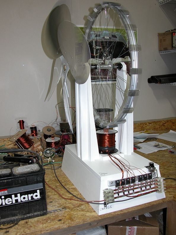
Thought I would write about something new to me but maybe old to you. The trigger circuit alternator. I have rewound all of the 9 lead coils @ 130' long and remounted them to the bike wheel. 16 transistors!

I also remounted the 2" X 3" magnets to the wheel 14 pieces in all. I know I am probably going to hear about this but I just have to see what the results are! Anyway so now I have 2 coils mounted so that they are timed for the same magnet passing. I left both coils wound with the trigger circuit and thought I would parallel them together. I got the prototype setup all ready to go and hooked up the charge chords to my 24 volt 720 AH bank.
\
I then ordered a very large 25 ohm var resistor which is now running the sg.
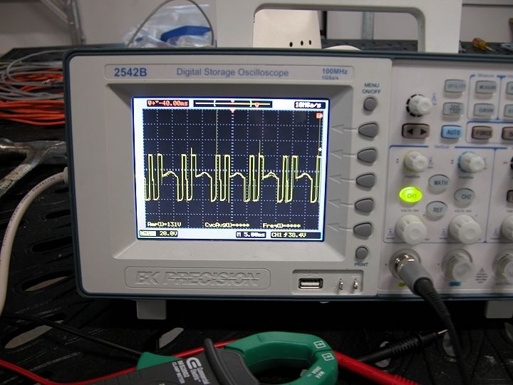
I am now operating @ 30 volts input 2.5 amp with wheel speed of 397 rpm and charging the big bank fairly well considering how massive it is using a 21 ohm resistance on the trigger circuit all 16. Everything is ice cold except for that big var resistor and that part does not mean anything. The heat is excess power that we need to control with the resistor to keep the transistors from burning up.
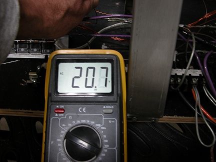
I would have never guessed that one trigger could provide this much power and could handle this many circuits.....not only that but many more also. I have not studied how much available power is there on the unused trigger circuit on the other coil but the AC voltage output is 20.3~ volts.
Probably enough to light a light bulb and possibly enough to rectify and run the machine? Is this what Tom Watson stumbled onto? I am only @ 347 rpm and he was @ somthing like 800 rpm. I am sure there is a very large output at this speed.
Thinking back to the duplicate SG I built not long ago to resemble the one from JB's lab.....the big fan. Just so you all know the fan has a huge purpose!
Thought I would write about something new to me but maybe old to you. The trigger circuit alternator. I have rewound all of the 9 lead coils @ 130' long and remounted them to the bike wheel. 16 transistors!
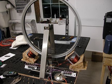
I also remounted the 2" X 3" magnets to the wheel 14 pieces in all. I know I am probably going to hear about this but I just have to see what the results are! Anyway so now I have 2 coils mounted so that they are timed for the same magnet passing. I left both coils wound with the trigger circuit and thought I would parallel them together. I got the prototype setup all ready to go and hooked up the charge chords to my 24 volt 720 AH bank.
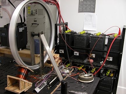
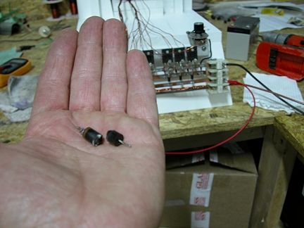
\
I then ordered a very large 25 ohm var resistor which is now running the sg.
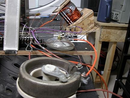
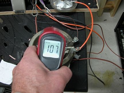
I am now operating @ 30 volts input 2.5 amp with wheel speed of 397 rpm and charging the big bank fairly well considering how massive it is using a 21 ohm resistance on the trigger circuit all 16. Everything is ice cold except for that big var resistor and that part does not mean anything. The heat is excess power that we need to control with the resistor to keep the transistors from burning up.
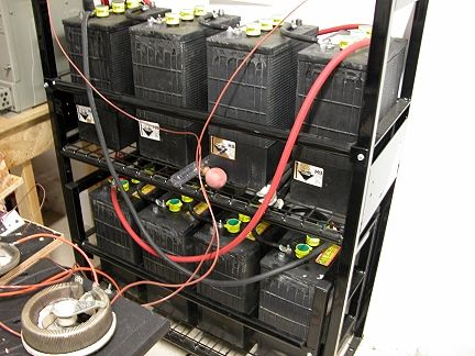
I would have never guessed that one trigger could provide this much power and could handle this many circuits.....not only that but many more also. I have not studied how much available power is there on the unused trigger circuit on the other coil but the AC voltage output is 20.3~ volts.
Probably enough to light a light bulb and possibly enough to rectify and run the machine? Is this what Tom Watson stumbled onto? I am only @ 347 rpm and he was @ somthing like 800 rpm. I am sure there is a very large output at this speed.
Thinking back to the duplicate SG I built not long ago to resemble the one from JB's lab.....the big fan. Just so you all know the fan has a huge purpose!

Comment