Hey Bud,
what size trigger wire are you using and can you measure the resistance of one of the windings? How many ohms are your individual base resistors? Can you post some scope shots?
To give you an idea, my 10 coiler is all 8 windings of 130' of #18. Each winding measures 1.0 ohms, so I have two windings in series for the trigger on the master coil. My base resistors are all 100 ohms and the master base resistor is a 300 ohm 100 watt wire wound rheostat with a 12 volt car taillight in parallel. The rheostat is set at about 150 ohms and is not the slightest bit hot. The tail light is about half brilliance and gets a little warm as you'd expect. I am running at 12 volts primary and charge batteries and see no need to run at higher voltages.
John K.
-
Hi John,min2oly,
Everything about this setup is icecold except for that resistor. All 16 transistors are triggered by that one trigger winding leaving the other one free. I did try to increase the resistance this morning and things cooled a little but I ran out of control on the var resistor @ 25 ohm. Will try something larger. I also have the ability to rewind the coil and change the trigger as the trigger is not litzed into the other 8 power windings....it is separate but follows the braid very tighly when wound. I could always wind a smaller trigger wire size or shorten it or add taps to the trigger to see what the best setup. Rewinding for me has become second nature and the time it takes is nill. Lots to consider and think about.
All in all I have made several serious mistakes over this past year but now I really understand the heart of what makes this thing tick. It is like anything else I have conquered in my life and that is you have to make all those mistkes first to really really learn it. You cannot get it by reading the book! Period! You have to live it! The best info I have received yet is the one small piece that John talks about and that is the as the magnet approaches the coil the current passes one way and stops as the magnet get centered on the coil......then the current travels the opposite way when the magnet leaves the coil within the trigger circuit. For me this is when the light bulb lit in my mind. It all makes perfect sence now. I can now move on.
BudLeave a comment:
-
Bud,
I'm interested in your findings with this. What John says is true.
my first thought is that if your resistors/pot is getting hot, then you have too many windings(volts/amps) on the trigger coil, we only need enough to bias the bases of all the transistors.
My goal with the larger builds has always been to aim for as little trigger winding as I can get away with and still have a good tuning range. My biggest quandry has been how thick/amps the winding should be for the multi-coil builds... I guess it's all in the math, how many resistors/watts needed in total to bias the bases... it's easier for me to just pull off a few feet at a time and test :-)
Keep us posted - thanks
PatrickLeave a comment:
-
Hey Bud,
Nice report. It sounds like to me you are just pushing way too much current there which is why your master base resistor is getting hot. One of the reasons is because you paralleled the trigger wires from both coils. You don't need individual trigger wires, but as a test try putting them in series instead.
You should also find that if you increase the resistance on the master base resistor the rpm will increase more.
Believe me, the path to OU is not by creating heat. You want everything to run cool and even the master base resistor should not get that warm. Every time you increase the primary draw you will need to retune the machine.
John K.Leave a comment:
-
Trigger Circuit Excessive Output
Hi All,
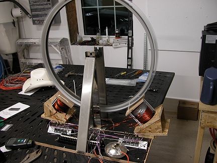
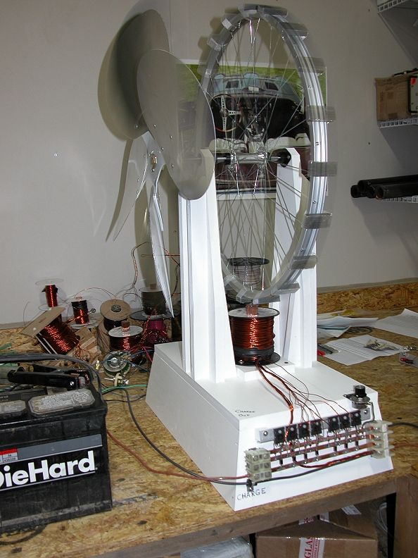
Thought I would write about something new to me but maybe old to you. The trigger circuit alternator. I have rewound all of the 9 lead coils @ 130' long and remounted them to the bike wheel. 16 transistors!

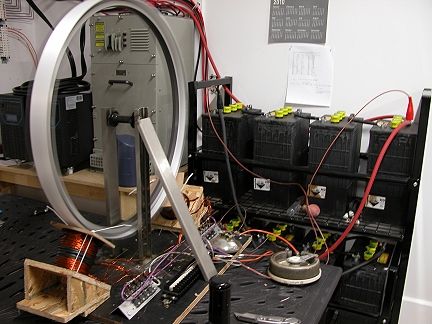
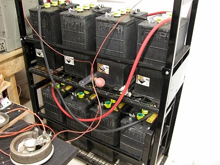
I also remounted the 2" X 3" magnets to the wheel 14 pieces in all. I know I am probably going to hear about this but I just have to see what the results are! Anyway so now I have 2 coils mounted so that they are timed for the same magnet passing. I left both coils wound with the trigger circuit and thought I would parallel them together. I got the prototype setup all ready to go and hooked up the charge chords to my 24 volt 720 AH bank.
\
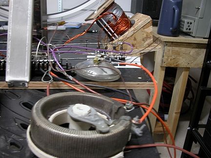
I then ordered a very large 25 ohm var resistor which is now running the sg.
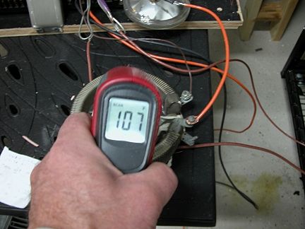
I am now operating @ 30 volts input 2.5 amp with wheel speed of 397 rpm and charging the big bank fairly well considering how massive it is using a 21 ohm resistance on the trigger circuit all 16. Everything is ice cold except for that big var resistor and that part does not mean anything. The heat is excess power that we need to control with the resistor to keep the transistors from burning up.
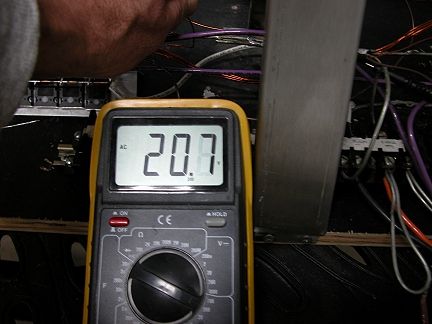
I would have never guessed that one trigger could provide this much power and could handle this many circuits.....not only that but many more also. I have not studied how much available power is there on the unused trigger circuit on the other coil but the AC voltage output is 20.3~ volts.
Probably enough to light a light bulb and possibly enough to rectify and run the machine? Is this what Tom Watson stumbled onto? I am only @ 347 rpm and he was @ somthing like 800 rpm. I am sure there is a very large output at this speed.
Thinking back to the duplicate SG I built not long ago to resemble the one from JB's lab.....the big fan. Just so you all know the fan has a huge purpose!
Leave a comment: