Announcement

Collapse
No announcement yet.

My first unit to achieve 1 for 1 charging!

Collapse
X
 
  • Filter
  • Time
  • Show
Clear All
new posts

  • My first unit to achieve 1 for 1 charging!

    I finally have a build that will charge a single identical battery with a single charge! It is my old mini 6 pole that has been rebuilt with 19 awg motor windings, and 23 awg trigger. I am running it with only 4 coils activated, as this seems to be optimum for running at 12v. I am getting 410v spikes, with 2 pulses per magnet. All components are running cool, including the charging battery. The unit starts at around 3900 RPM, takes about 3 hours or less to charge a 5ah battery, and at the end of the run the RPM is at about 2950. I am getting battery COP's of over 2 with both 5ah and 9ah batteries!
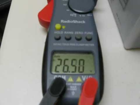
    Here is a pic:

    Click image for larger version

Name:	18awg6pole 002.jpg
Views:	1
Size:	95.0 KB
ID:	50885

    November 1st was an exciting day, as that was the day I was first able to reach this milestone!

    -Woody
    Last edited by Woody; 11-03-2012, 06:56 PM.
    "It's not a mutiny if the commander is leading it!" - Wally Schirra, Commander Apollo 7

  • #2
    Woody Congrats, I Remember when i got my ssg running. I did the bedini dance in the dinning room !!!

    Comment


    • #3
      Hi Woody,
      Nice and neat set-up...unlike my lab at home...
      rgds,
      Faraday88.
      'Wisdom comes from living out of the knowledge.'

      Comment


      • #4
        @Woody,
        Your build looks great. Congratulations!
        What was the current draw from primary, for charging in 3 hours your 5 amp battery?
        Wishing all the best,
        Teo

        Comment


        • #5
          Thanks all!

          @axxelxavier,
          My draw on primary is .64a. The input to secondary is .155a. Trigger resistance is 52 ohms. After 4 runs the secondary is showing increasing capacity. The master coil is not advanced at all. I have tested the unit at 24v and 36v, but have alot more to investigate at those higher voltages. I'm just beside myself to finally be able to do 1 for 1.

          My primary starts at about 13.2v and is at about 11.9v by the time the secondary reaches about 14.6v. The primary recovers to about 12.35v.

          -Woody
          Last edited by Woody; 11-05-2012, 09:17 AM.
          "It's not a mutiny if the commander is leading it!" - Wally Schirra, Commander Apollo 7

          Comment


          • #6
            Woody...that's awesome man! Machine looks great...

            What are you going to work on now?

            Comment


            • #7
              Excellent news Woody .. nice one! I've been lead to believe that we should be aiming for one pulse per magnet, but I see that you are getting results from two. How does your machine perform with just one spike? Any thoughts on this? Rob

              Comment


              • #8
                @Woody,
                Thank you for your reply.
                can you show us more pictures, from different angles, please?
                Wishing all the best,
                Teo

                Comment


                • #9
                  @Branch- Thanks! I just ordered some rectangular SmCo magnets that I intend to arrange in the super pole configuration on the rotor. That will be my next modification. Also, from the initial tests at 24v, it appears that further enhancements manifest at the higher voltages, such as being able to activate the other 2 coils while actually lowering the current draw. I still need to do more work on this though.

                  @Rob- I have heard that the number of spikes that are optimum really varies from one build to another and
                  I can verify that maxim. My bike wheel likes 1 spike, but this 6 pole running at 12v with 4 coils activated really likes 2 spikes. When I reduced the trigger resistance down to the point that I had 1 pulse, the current draw on the primary was huge, the thing ran super fast, and components heated up. Yes, the spikes were huge too (800v) and the charging was obscene, but it crossed the line. The primary discharged too fast, and the charge to secondary was largely surface charging with traditional current. We want radiant and some traditional positive component together to obtain the best results. It has taken quite a bit of tweaking on this build, but I seem to have finally struck a good balance.

                  @Teo- I am away from the lab for a bit, but when I get back I'll take some more pics and post them.


                  A bit more detail- The coils are 212 turns of 19awg motor windings and 23awg trigger. Base resistors are 100 ohms, and the diodes are higher voltage. The smaller is the 1N4007, the bigger one is a 3a 1000v diode. also, I have 4.7k ohm resistors in series with the NE-2 neons.
                  "It's not a mutiny if the commander is leading it!" - Wally Schirra, Commander Apollo 7

                  Comment


                  • #10
                    Teo- Here are some more pictures of the machine.

                    Click image for larger version

Name:	19awg6pole 004.jpg
Views:	1
Size:	92.5 KB
ID:	45020Click image for larger version

Name:	19awg6pole 005.jpg
Views:	2
Size:	92.4 KB
ID:	45021

                    Click image for larger version

Name:	19awg6pole 001.jpg
Views:	1
Size:	91.6 KB
ID:	45022Click image for larger version

Name:	19awg6pole 002.jpg
Views:	1
Size:	91.8 KB
ID:	45023

                    The yellow coils on the rear of the machine are not being used right now. They are generator coils, and I usually have a second rotor mounted on the shaft. I have that assembly in place to provide a third bearing which stabilizes the long shaft, reducing vibration.

                    -Woody
                    Last edited by Woody; 11-09-2012, 03:14 PM.
                    "It's not a mutiny if the commander is leading it!" - Wally Schirra, Commander Apollo 7

                    Comment


                    • #11
                      Hi Woody. Have you had the generator coils working at all? Please can you explain how they work a little bit. Thanks .. Rob

                      Comment


                      • #12
                        Rob-

                        The generator coils produce A/C, and provide a means of loading the system mechanically which reduces the current draw on the primary while also extracting useable electrical energy. I have used the output of the generator coils by rectifying the A/C, and then sending it to a capacitor for dumping to the primary. This produces a nice increase in COP. I have some videos of the unit in action, but they were shot before my most recent rebuild with the 19 gauge coils. Here is a short video showing the gen coils and pulser in operation. In this video, I am running at 24v.


                        -Woody
                        "It's not a mutiny if the commander is leading it!" - Wally Schirra, Commander Apollo 7

                        Comment


                        • #13
                          Hi Woody, I thought that they were intended to do something like that. Thanks for the vid. Do you have a circuit diagram / schematic for this build by any chance? I'm getting a COP of around 1.75 on my chargeing batteries at the mo, but my overall system COP is a poor 25%, so I figure I need to start thinking about how to make it more efficient, and capture some of that wasted energy. R

                          Comment


                          • #14
                            Hey Rob,

                            The SSG part of the circuitry is just standard single trigger, multiple coil layout. Nothing special at all. Here is a cheesy hand drawn diagram of the cap pulser. Sorry it's kinda lame, but it should explain it.

                            Click image for larger version

Name:	cap pulser circuit diagram 001.jpg
Views:	1
Size:	84.6 KB
ID:	45038

                            -Woody
                            "It's not a mutiny if the commander is leading it!" - Wally Schirra, Commander Apollo 7

                            Comment


                            • #15
                              Hi Woody, nice one for the schematic. Have you tried doing the timing using electronics, rather then the wheel? This part looks a bit unelegant to me. Btw, a quick progress report on my own efforts: I tried experimenting with different sweet spots after reading your original post at the top of this thread. I tuned it into its 3 pulse sweet spot yesterday, and got an outstanding COP (for me at least) of 2.21 on the battery, and .65 overall. I'm gonna try the 4 pulse sweet spot tomorrow, and see if I get the same kind of COP improvements as I did at three. Maybe unity isn't as far off for me as I thought ( .. he says optimistically). Rob

                              Comment

                              Working...
                              X