If this is your first visit, be sure to
check out the FAQ by clicking the
link above. You may have to register
before you can post: click the register link above to proceed. To start viewing messages,
select the forum that you want to visit from the selection below.
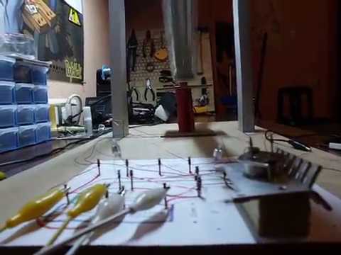
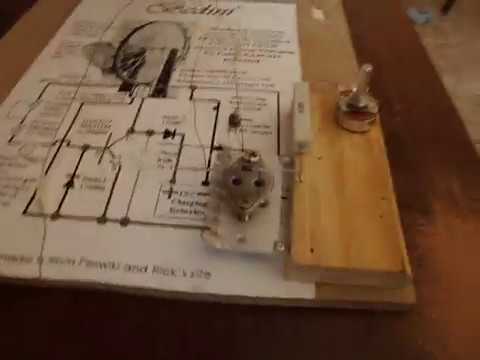
Dump (get rid of) the daftman layout - great for visualisation - poor for good charging/tuning. daftman layout is perhaps why many fail.
solder everything directly to the transistor.
put a capacitor in parallel w/ the power supply.
put nice thick leeds from circuit to the battery (no small alligator clip leads)
put the circuit right on the coil.
----------------
transistor may be too big for that small wire sub w/ mje130007g
and sub E/B diode w/ 1N914
or...
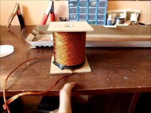
for that coil and that wheel the thinnest wire "I" would use is 20awg (0.81)
if you're going to replace it, go w/ 18awg
------------------
I like your clean table. This build is a VERY good first step!
Kind regards,
Patricio
1 Where to put the capacitor? In primary or secondary battery
- Parallel to your power supply.
2 Set LED thick. No where to put them.
- Not LED - "Lead" the wire leads. The wire that goes DIRECTLY from collector diode to charge battery, and the wire that goes directly from primary + to charging - . I spelled wrong (leeds)
3 Switch right in the coil circuit.
- Not "switch", Mount the circuit onto the coil or right next to it. the energy is traveling too far from your coil to the circuit.
4 You could spend some diagram with details
- No change in diagram, just get rid of all that extra daftman wire. solder your emitter/base diode right onto the transistor etc...
solder everything right onto the transistor
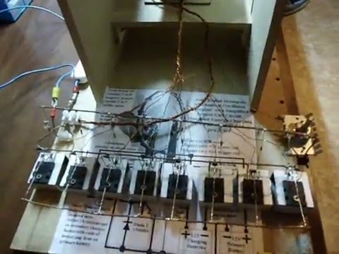
here is an example picture where everything is soldered as close to the coil as possible:
[ATTACH=CONFIG]2428[/ATTACH]
notice thicker wire lead from output diode to charge battery terminal.
1 Where to put the capacitor? In primary or secondary battery
- Parallel to your power supply.
2 Set LED thick. No where to put them.
- Not LED - "Lead" the wire leads. The wire that goes DIRECTLY from collector diode to charge battery, and the wire that goes directly from primary + to charging - . I spelled wrong (leeds)
3 Switch right in the coil circuit.
- Not "switch", Mount the circuit onto the coil or right next to it. the energy is traveling too far from your coil to the circuit.
4 You could spend some diagram with details
- No change in diagram, just get rid of all that extra daftman wire. solder your emitter/base diode right onto the transistor etc...
solder everything right onto the transistor
here is an example picture where everything is soldered as close to the coil as possible:
[ATTACH=CONFIG]2428[/ATTACH]
notice thicker wire lead from output diode to charge battery terminal.
 Tweet
Tweet
 Bedini oscilador radiante


Comment