Announcement

Collapse
No announcement yet.

Advanced ZFM Explorations Part 3

Collapse
X
 
  • Filter
  • Time
  • Show
Clear All
new posts

  • #16
    ZFM Coil Blitzen

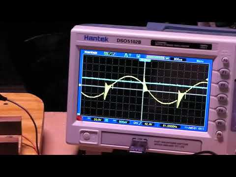
    Well, the prior BEMF experiments were very useful in helping to the design the newest coil version with 4 strands of AWG#23 magnetic wire. The modified coil design was based on many experiments over the past year that all enhanced the understanding of this DC motor.

    So there have been multiple tests and experiments where the primary goal was to extract relevant information, some may question this experimental approach, but in the end it is no different than any other research that does not have a book such as "ZFM Design for Dummies" as a reference point.

    The specific coil design information will be very light for the time being, however the modified coil has been upgraded with with specific dimensional end points that allow a much more accurate means of duplicating coils to specific design dimensions. Don't really need a fracken 3D printer when simple tools, PVC cement and inexpensive PVC pipe will do the job for low budget experimentation, albeit that the rotors have to be machined, the shafts purchased and machined, the Bipolar switch built and the Neo's purchased ( BTW N52 Neo's in certain sizes are hard to get with our current political spiff with China).

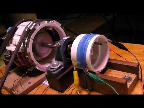
    Fortunately, a small measure of forethought was put into the current design and many components can be reused many times. In this configuration the 6 Pole rotor, initially with 2"x3/4"x3/8" N52 Neo's and modified with an additional 1-1/2"x3/4"x1/8" glued on top to give the appropriate height along with the modified coil design.

    The ZFM is a very flexible and forgiving motor - so the question here is whether it will operate with only a single coil?

    The answer is Yesss! But does it perform and does it perform beyond expectation?

    Preliminary testing demonstrates that it will handle the normal 950 gram load easily with a performance efficiency of around 46% at 24 volts. Certainly, with additional tuning it will easily pass over the 50% efficiency threshold. Impressive for just a single coil!. One can only speculate what the future addition of another coil or two or three will yield.

    No Pics or Video or run data for now...

    Until the next episode - Happy Holidays,
    Yaro
    Last edited by Yaro1776; 12-23-2020, 05:18 AM. Reason: Correct Neo Size
    Yaro

    "The Universe is under no obligation to make sense to you." -Neil Degrasse Tyson

    Comment


    • #17
      ZFM Coil Blitzen 2

      The past week or so has been spent working with the timing for this 6 Pole 1 Coil configuration and the performance of the single coil design has been fairly impressive in that it duplicates the best efforts that were demonstrated by the 2 and 3 coil 6 Pole configurations. The new coil design is approaching or is at what can be considered nearly optimal for the 6 Pole rotor outfitted with the 3/4" wide Neo's. Below are the data points and two Oscope pics from the experiments conducted 12/31/20 to close out the year on a positive note.

      Experiment 1 at 24 volts and 900gr Load

      Click image for larger version  Name:	pic_354_1-1.jpg Views:	0 Size:	116.3 KB ID:	73268

      Experiment 5 at 24 volts and 0gr Load

      Click image for larger version  Name:	pic_354_4-1.jpg Views:	0 Size:	113.3 KB ID:	73269

      The timing parameters for this experiment were in a comfortable operating zone and could be pushed a bit further, however the above are running in a very stable zone. Below are the five data points from the experiment.
      RPM Load (gr) Output(watts) Volts Amps Input(watts) Eff %
      2697 900 15.80 24.06 1.23 25.60 53.4
      2307 1250 18.77 24.23 1.63 39.49 47.5
      2333 1225 18.60 24.20 1.53 37.03 50.2
      3270 415 8.83 24.01 0.73 17.53 50.4
      3886 0 0 23.89 0.30 7.17 0.0
      The above results are a definite indicator of progress for this ZFM version. Overall the data points from these and other experiments with this configuration demonstrate an overall range of power efficiency between 45% to 55%.

      Prior to mounting the second coil a short operational video and pictures of this assembly will be posted.

      Thank you for your attention and Happy New Year - phew, glad 2020 is receding rapidly in the rear view mirror.

      Yaro
      Yaro

      "The Universe is under no obligation to make sense to you." -Neil Degrasse Tyson

      Comment


      • #18
        ZFM Ohmic Quandary Continued - Single Coil

        The following is a continuation of the Ohmic Quandary experiments, but with only one coil of the modified design mounted on the ZFM motor body and using the 6 Pole Rotor from the previous post. A quick look at this configuration can be seen below. Essentially the coil is wound with 4 strands of #23 magnetic wire. The resistance for each individual strand is 2.5ohms. The coil holder has thin PVC strips cemented to the holder to provide dimensional end control to the length of the coil and has a trial dimension of 48 degrees of arc based on a number of previous experiments.

        ZFM with Single Coil

        Click image for larger version  Name:	IMG_1706.JPG Views:	0 Size:	689.7 KB ID:	73291

        The purpose of this experiment is to demonstrate how progressively adding parallel strands to the circuit wiring of the coil impacts the overall performance of the single coil configuration. Presented below are 4 Oscope screen shots that are representative of this parallel strand configurations. Each pic is self explanatory with the full data set following the pics.

        Click image for larger version  Name:	pic_358_1.jpg Views:	0 Size:	121.4 KB ID:	73292

        Click image for larger version  Name:	pic_358_2.jpg Views:	0 Size:	120.7 KB ID:	73288

        Click image for larger version  Name:	pic_358_3.jpg Views:	0 Size:	122.2 KB ID:	73289

        Click image for larger version  Name:	pic_358_4.jpg Views:	0 Size:	117.3 KB ID:	73290

        The following data set is consistent with prior experiments in that there is really very little difference in value as the total coil parallel resistance is changed from 4 strands down to 1 (2.5ohms, 1.25ohms, 0.833ohms and 0.625ohms).
        RPM Load(gr) Output(w) Volts Amps Input(w) Strands
        4607 0 0 14.96 0.64 9.57 4
        3386 365 8.04 15.13 1.72 26.02 4
        4591 0 0 15.01 0.65 9.76 3
        3140 370 7.56 15.11 1.75 26.44 3
        4526 0 0 15.01 0.64 9.61 2
        2874 375 7.02 15.11 1.77 26.74 2
        4338 0 0 15.00 0.57 8.55 1
        The voltage was limited to 15 volts to keep the RPM under 5000 and the single strand coil config stalled with the 375gr load at this low voltage. For now, three different rotor and coil configurations have been tried with the similar results with regard to the operational performance. It will be of great interest to experiment with coil additions in the near future.

        Thanks for your attention,
        Yaro
        Attached Files
        Last edited by Yaro1776; 01-09-2021, 01:36 PM.
        Yaro

        "The Universe is under no obligation to make sense to you." -Neil Degrasse Tyson

        Comment


        • #19
          ZFM Video 6 Pole 1 Coil

          This post completes the initial experiments with the modified single coil ZFM configuration. The wiring configuration of this coil is all four strands in series with a total resistance of 10 ohms. The net result is a smooth running motor that holds promise for the next set of experiments with two opposing coils.

          Data from this set of tests all without load.
          RPM Load Output(w) Volts Amps Input(w)
          2048 0 0 24.08 0.14 3.37
          3000 0 0 36.04 0.21 7.58
          3907 0 0 48.02 0.30 14.41
          4768 0 0 60.02 0.37 22.21


          Upcoming will be the twin coil configuration of this single 4 strand coil design. It remains to be seen if the twin coils increase the performance and the efficiency of the ZFM.

          Thank you for your attention,
          Yaro
          Yaro

          "The Universe is under no obligation to make sense to you." -Neil Degrasse Tyson

          Comment


          • #20
            ZFM Video 6 Pole 2 Coil

            The modified coils and holders were installed in the ZFM body with the normal 6 Pole rotor. The 2 Coils are nearly identical in that after the final winding of the second coil yields 2.5 ohms per strand. The coil positioning was accomplished using a calibration disc to space the coils 180 degrees apart. The positioning was checked by applying momentary 12v DC to each coil and having the rotor lock in to the coil pole. This calibration is very close to dead on.

            Still in the process of testing various wiring patterns, but the first experimental runs after tuning yielded an operating efficiency that consistently reached the 60% mark. These first experiments were with all four strands of the coil wired in Parallel and then connected in Series with the other coil. The total series resistance is 1.25 ohms and the performance is robust at 27 volts yielding 30 watts of output power. The limitations of the torque testing arrangement prevent pushing the ZFM further.

            The peak efficient power band at 27v is between 60% and 80% of the 4500 RPM unloaded speed.

            A short show and tell video was created to give everyone a flavor of this ZFM and can be viewed below.


            Three other wiring configurations will be tested to record performance under load for comparison purposes. It is anticipated that they all will perform well with efficiencies just below the above described Parallel configuration.

            Thanks for your attention,
            Yaro
            Yaro

            "The Universe is under no obligation to make sense to you." -Neil Degrasse Tyson

            Comment


            • #21
              6 Pole and 4 Pole ZFM Recap

              The 6 Pole rotor with 2 opposing Coils variant of the original 4 Pole with 2 opposing coils ZFM is a very similar motor but with some differences in configuration. The differences are primarily in the Neo magnet configuration. The 4 Pole is configured with N-S-N-S Neo’s with the N-N and S-S Neo’s opposing each other, whereas the 6 Pole is configured with a N-S-N-S-N-S Neo’s creating a N-S opposing polarity.

              The original 4 Pole Coils used four 20 AWG strands in series for a 3 ohm resistance for each 90 degree coil and a total series resistance of 6 ohms. This ZFM would perform over a wide range of voltage with good torque to achieve about 35% to 40% efficiency as configured. At high voltages (60v) this ZFM would perform at well over 13,000 RPM. A later version using an 82 degree Coil arc improved on the performance.
              The first 6 Pole configurations used two or three coils that were about 43 degrees in arc length according to the work of Ron Cole. This coil arc dimension was later determined to be on the short side, however both coil variants (1, 2 and 3 Coils) were tested with several rotor configurations and were able to achieve efficiencies of up to 45% to 50%. Each of the coils used the same 20AWG magnetic wire with two strands – in series this yielded 2.1 ohms per coil.

              The last 6 Pole variant utilized a coil configuration of four strands 23AWG magnetic wire with an individual strand resistance of 2.5 ohms or 10.0 ohms per coil. The physical arc length for this coil was increased to 48 degrees with a much tighter tolerance of fabrication and assembly. This configuration with two opposing coils was able to operate at 55% to 60% efficiency with particular strand configurations.

              Neo Magnets
              Many different Neo sizes were used in the testing, with the later test experiments using magnets that were 1/2”, 3/4” and 1” widths and typically 1/2” thick. The lengths varied from 1”, 1 1/2” and 2”. The width of the Neo is an important factor in its relationship and interaction with the Coil Magnetic Poles. Normally N52 Neo’s were specified when available.

              Virtual Coil Poles
              The coil arc dimension is a critical factor to the overall performance of the ZFM. Multiple experiments with various magnet widths confirmed that the actual magnetic pole that influences the rotor Neo magnets occurs beyond the physical dimensions of the individual coil ends. A simple ZFM experiment with a single coil and a two pole rotor with a degree wheel will demonstrate this. The gap between the Neo’s leading edge and the coil is about 0.040”-0.060".

              For example, a 6 Pole rotor has a 60 degree spacing between the centers of the mounted Neo magnets and a 60 degree physical arc length coil will yield about a 68 to 75 degree virtual magnetic pole arc length depending on the width of the Neo magnets.

              Therefore, the physical arc length of the coil becomes a critical factor when matching the relative positions of the Neo Rotor Poles and the Virtual Magnetic Poles of the coil. Since each coil has a Virtual North and South Pole when energized, then the position of each Neo should be very close to perfect with the coil’s Virtual Poles.

              The next post will amplify on the Duty Cycle and the Ohmic Quandary.

              Appreciate your attention,
              Yaro


              Last edited by Yaro1776; 11-12-2021, 05:40 AM. Reason: Typo for air gap between coil and Neo
              Yaro

              "The Universe is under no obligation to make sense to you." -Neil Degrasse Tyson

              Comment


              • #22
                6 Pole 2 Coil ZFM Recap - Part 2

                The Ohmic Quandary
                In 1989 Ron Cole performed a series of experiments with a two pole rotor with Neo magnets and a single 4 strand air coil. The experiments started with one strand and then progressively added additional strands of the same length in parallel, while noting the resulting Amperage for a constant dc voltage as the Resistance was decreased.

                According to established circuit theory the total Amperage should increase dramatically as the parallel strands were added – meaning if the resistance of the circuit is decreased by a factor of four, then the Amperage increase at a constant voltage should reflect that change.

                The results of Cole’s experiment were counter to accepted theory. The maximum Amperage reading with 4 strands yielded a very slight increase in numerical value (10%) over 1 strand. From these data points Cole inferred that the torque output would markedly increase without any amperage penalty.

                The resultant motor produced power with efficiencies well over 100% according to the information and documents in the late John Bedini’s files. Of course, all of these and above claims should be viewed with some skepticism until they are replicated. The Cole motor is an actuality a variant of the ZFM and one can see Bedini’s influence throughout this design.

                To initially confirm some of Cole’s observations and findings five different coil configuration were tested this past year and all five experiments confirmed his findings with respect to the parallel resistance amperage values remaining relatively constant as additional parallel strands were added. The additional parallel strands increased RPM and overall efficiency in the majority of experiments.

                Further experiments will be performed in the future to further refine the understanding of this anomaly that contradicts existing theory. This straw may turn out to bring the camel to its knees.

                Duty Cycle
                Over the course of the past few years many experiments have been completed with multiple combinations of rotors and air coils. The air coil has an important characteristic in that the current rise time and dissipation upon power off are very rapid. This characteristic enables the power-on cycle to be extended way beyond common practice.

                For example, for a 60 degree rotor Neo separation the duty cycle can be extended up to and a bit beyond 50 degrees. To some degree this is also influenced by the Neo width and the wiring pattern of the coils.

                For specific ZFM motor configurations there is a definite increase in power capability and efficiency. There are too many other details in all to cover in this short synopsis.


                Thank you for your attention,
                Yaro

                Yaro

                "The Universe is under no obligation to make sense to you." -Neil Degrasse Tyson

                Comment

                Working...
                X