Announcement

Collapse
No announcement yet.

Advanced ZFM Explorations Part 3

Collapse
X
 
  • Filter
  • Time
  • Show
Clear All
new posts

  • Advanced ZFM Explorations Part 3

    The Ohmic Quandary

    The last thread (Part 2) ended on a positive note demonstrating that with proper tuning the overall ZFM efficiency could easily be pushed to the 50+% level with the 6 pole rotor and three coil (bifilar strand configuration). Certainly the lessons learned in this three coil effort could be applied to the two pole coil and four pole rotor configuration to improve its performance to a higher level.

    All that aside, one experiment that was not included in the prior thread was the single wire versus bifilar comparison for the 6 pole three coil bifilar configuration, so this thread is devoted to the direction of experimenting with various coils and multifilar coil strands. The Bedini/Cole association lasted many years and certainly created a synergy of innovation between them. John B was a prodigious experimenter with a passion for physical results and minimal technical documentation - his passion was centered in the exploration and discovery, while Cole, ever the experimenter, did understand the value of documentation and its importance to future replications.

    R Cole produced a schematic of a coil configuration experiment that took a quadfilar strand Coil wind and proceeded with an experiment that at a given voltage tested the various amperages in parallel of each added strand to the coil. The experimental results are somewhat mind blowing in that while the overall resistances of each parallel strand addition were calculated in the classical method the overall operating amperages for each strand addition were not. Contrary to expectation.

    Here is his data sheet.

    Click image for larger version

Name:	Air Core Trifilar.jpg
Views:	525
Size:	96.8 KB
ID:	72865

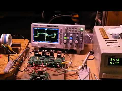
    So this intriguing information from R Cole's experimentation triggered a "what if" question and it was applied to two experiments with the existing 6 Pole ZFM. Here is a schematic of the basic ZFM configuration used in these experiments.

    Click image for larger version

Name:	6Pole Coil Config.jpg
Views:	438
Size:	276.9 KB
ID:	72866

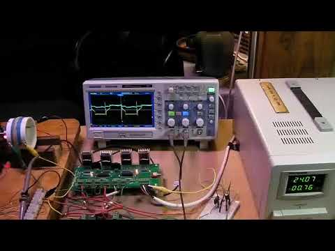
    EXPERIMENT 1 Single Strand
    Three bifilar coils, #20AWG, with 1.1 Ohm resistance per single coil strand with 6 pole rotor. Connect only one strand per coil in series. Total series R equals 3.4 Ohms.
    RPM Load(gr) Output(w) Volts Amps Input(w) Eff(%)
    2905 0 0.00 24.04 0.42 10.10 0.0
    2572 460 7.70 24.07 0.75 18.05 42.7
    2069 1020 13.74 24.07 1.29 31.05 44.2
    1636 1500 15.97 24.04 1.73 41.59 38.4
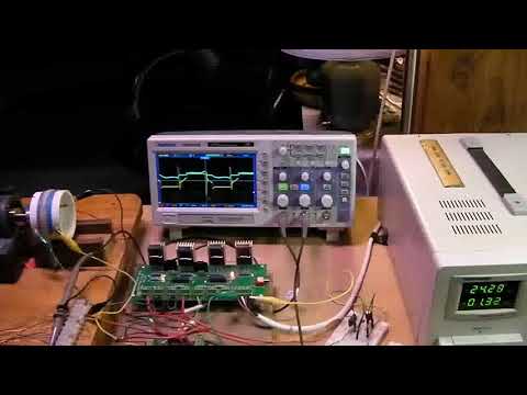
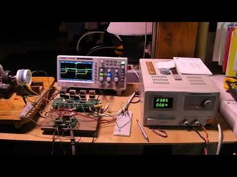
    Experiment 2 Bifilar Strand
    Same config as first experiment, but with coil strands in parallel with 0.55 Ohm resistance per coil. Coils wired in series for a total R of 1.7 Ohms.
    RPM Load(gr) Output(w) Volts Amps Input(w) Eff(%)
    3029 0 0.00 24.02 0.43 10.39 0.0
    2717 500 8.84 24.03 0.82 19.70 44.9
    2339 1050 15.99 24.05 1.33 31.99 50.0
    2035 1520 20.13 24.06 1.75 42.11 47.8
    These two experiments were run on three separate days with all the resulting data demonstrating the same type of behavior and values. Certainly, these preliminary experiments support the results of at least two parts of Cole's data and his supposition that the coil wiring configuration yields results that do not conform to the classical methods of measurement or calculation. So is Ohm's Law out the window or are there other unidentified influences at play with the ZFM???

    In a nutshell, these two experiments demonstrate that changing the overall resistance of a coil by 50% with equal length strands, and then wiring the remaining motor coils in series increases the performance in terms of speed (RPM) with only a minor change in total Input Power. This is way over my primitive level of understanding for at least the time being.

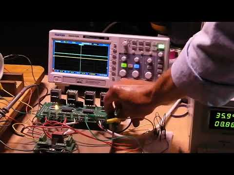
    There is a video of the above experiments in the works - unedited version is well over 15 minutes in length due to a lot of dead time taking the Load readings. I will post this at a later date when a decision is reached to post an edited or unedited version.

    This new project, with associated experiments, should keep me occupied for some time and expect to initiate more of this work later this summer.

    Thank you for your kind attention,
    Yaro Stanchak


    Yaro

    "The Universe is under no obligation to make sense to you." -Neil Degrasse Tyson

  • #2
    Hi Yaro,

    I know Ron labeled this as ocuring in a "Faraday" motor, but I always suspected that this also occurs in the other type pulse motors as well .................. even when some iron is present. Adding extra power strands to a SSG doesn't seem to increase input current in a linear ratio either. I always assumed this was due to a mutual inductance effect with pulsed currents? And I don't know if it matters or not if each strand has an individual switching device or if only one device is used for several strands. Lots of room for experimentation.

    When my grandson and I built the two stage mechanical oscillator, we tried several different configurations on the SSG Bedini wheel we were driving it with. The coil was 3 winds of 130' # 20 wire and 1 strand of 130' #23 wire. These were all litzed (twisted together). We started with 2 #20 power windings, 1 #20 recovery winding, and one #23 trigger winding. Each power winding was switched by it's own MJL21194 transistor. As best I can remember, the current draw was around 1 amp and performance wasn't very good. After some experimenting, we wound up with all three 130' #20 power wires switched by one FET and a hall device and the single 130' #23 winding was used as a power recovery coil. The RPM and power output was much greater, but the current draw was about the same or slightly less!

    This has been some time ago and I didn't record measurements, so I can only speak in generalities. But I was amazed that the current draw behaved the way it did.

    Gary Hammond,

    Comment


    • #3
      Hello Gary,

      Interesting results from your experiment that point out area's that can produce puzzling results that do not conform to classical expectations. There is quite a bit of room here for further in depth experimentation. Unusual that configuring your coil strands in parallel jacked up the performance without a power penalty.

      During my last experiments I did rewire the one strand config so that all the air coils were in parallel and the ZFM ran up to 4100 RPM at 1.87A at 16.1v without a load, but with very little torque in comparison to the prior two experiments. One set of transistors became hot to the touch so the experiment was stopped after documenting with a short video. The scope wave pattern was also very different with the parallel coils. I will have to try this again before I take down this ZFM config.

      It appears that the parallel strand wiring and series combination for the coils may have some interesting benefits to the ZFM configuration and performance.

      Yaro
      Yaro

      "The Universe is under no obligation to make sense to you." -Neil Degrasse Tyson

      Comment


      • #4
        ZFM Experiments 1 and 2 Videos

        So as a follow-up to the first post of this thread I decided to post the two unedited versions from the Experiments as described in the first post. The deadtimes in the videos are a bit of a distraction, but I thought that the process of doing the motor testing, while doing a simultaneous video of it would be useful. Challenging at times...

        Experiment 1


        Experiment 2


        So these videos do provide a look at what happens when the coil configuration is modified for the ZFM. A Big Deal, to some that watch carefully. The major point here is that the addition of another equal length strand to the coil in a parallel mode, then in series with the other coils improves the performance, as in noticeably. Major point here is that the resistance has been halved, yet the input power remains relatively the same. Really?

        According to Bedini/Cole, this unusual behavior continues as one adds wire strands, at least up to four. This modification and subsequent improved performance of the ZFM does not make sense, particularly when one considers that the parallel resistance continues to be reduced while the input amperage remains the approximately the same!

        Hence, the Ohmic quandary, specifically when parallel is combined with series. This certainly promotes further investigation for those that are skilled... in the unknown. What a laugh...

        Yaro

        .
        Yaro

        "The Universe is under no obligation to make sense to you." -Neil Degrasse Tyson

        Comment


        • #5
          ZFM Experiment 3 Video Parallel Coils

          After reviewing the prior Videos (Experiments1 and 2} it became obvious that the comparison needed a Parallel circuit Experiment for the single strand coils to complete the experimental set.

          The overall motor resistance came in at 0.4ohms, rather low. So it seemed prudent to perform the experiment with single wire mode to evaluate the operational characteristics (amperage draw) created by the wiring modification. After a couple of preliminary runs at 16v the voltage was increased to 20v and then subsequently to 24 volts. A brief foray into the higher voltages yielded amperages that were a bit too high for the BiPolar Switch board due to the overheating of a couple of transistors. The suspicion was that in Bifilar parallel mode the operating amperage may be way too high for comfort, at least using the classical approach.

          So, for both voltages the acceleration to speed (no load) was fairly slow, with the speed continuing to climb for an extended period of time.

          Test1 20.01v 2.23A 5600RPM
          Test2 24.01v 2.61A 6780RPM


          The video demonstrated a couple of interesting characteristics:
          1) Motor amperage remains relatively the same throughout the length of the acceleration curve
          2) The oscope amperage trace rises very rapidly and has a squarish shape.
          3) The oscope voltage trace depicts a sinusoidal shape. It appears that the BEMF nearly totally overrides the power supply voltage. This was further checked by operating with only one firing polarity verifying this observation.
          4) This configuration does not have the bottom end torque as the configurations of the prior Experiments.
          5) The motor coils did not overheat during the length of test run.
          6) A previous day's torque test, with a 1000gr load at 24 volts, brought the motor to a stall at 3.2A
          7) There may be other quirks at the higher voltages, but for now we are good.


          So, I am done with this config for now and maybe moving on to other mysteries. But then, the Bifilar mode with all the coils in parallel beckons - does it conform to the prior ways, hmmm, maybe or not.

          Happy Summer,
          Yaro
          Last edited by Yaro1776; 06-27-2020, 03:02 AM. Reason: Fleshing it all out
          Yaro

          "The Universe is under no obligation to make sense to you." -Neil Degrasse Tyson

          Comment


          • #6
            ZFM Experiment 4 - All Coil Strands in Parallel

            Upon review of the previous Experiment 3 with the coil single strands in parallel, I would be remiss in not fleshing this out and putting all the strands in parallel. Just to observe if the additional wires conform to the results in the of Experiments1 and 2. I won't post the video for this experiment since it is nearly identical in operation and data values as Experiment 3.

            Each of the three coils with the bifilar parallel strands were wired in parallel to yield about 0.2ohm of total circuit resistance. This winds up being a calculated value since the DVM's accuracy is out the window at very low resistances. So in this experiment the total resistance value is halved from that of the prior experiment. Will this all in parallel configuration demonstrate the same operational quirk? Yesss....

            Test 1 - 20.00v 2.25A 5555 RPM
            Test 2 - 24.01v 2.58A 6957 RPM

            These results are very close to Experiment 3 even though the resistance has been halved. The RPM is again improved! So there is something going on here that is repeatable.

            The next set of experiments will focus on a more detailed look at the strand configurations using a two Coil motor body and the existing 6 pole rotors on hand - should be interesting to see how this all plays out with quadfilar coils.

            Until next time, and have a great 4th of July,
            Yaro


            Yaro

            "The Universe is under no obligation to make sense to you." -Neil Degrasse Tyson

            Comment


            • #7
              Hi Yaro,

              Very interesting results. Especially test 2 at 24.01 volts. Compared to Experiment 3, the current dropped slightly and the RPM increased!

              Gary Hammond,

              Comment


              • #8
                Hello Gary,

                Thanks for the reply, and yes the results from these experiments are intriguing enough that more coil config experiments are under way to further proof and replicate these observations.

                Yaro
                Yaro

                "The Universe is under no obligation to make sense to you." -Neil Degrasse Tyson

                Comment


                • #9
                  The Ohmic Quandary Phase 2 with Twin Coil Config

                  The purpose of this next phase of experiments is to duplicate/replicate the prior experiments of the Bedini/Cole Anomaly with another motor body and coil configurations. This ZFM configuration will utilize two diametrically opposed coils while retaining the current 6 pole motor rotor and current electronics. This new coil configuration will initially utilize the existing coils to establish a baseline for comparison purposes

                  The first 3 coil machine was a balanced design utilizing the harmonious 120 and 60 degree angles, whereas in the new Opposing Coil configuration there is a combination of 180 and 60 degree angles. Lets see how this works out with the first baseline tests using the prior experimental format. Do the results validate the prior experiments?

                  Test1 - Single Strands in Series (2.1 ohms)
                  RPM Load(gr) Output(w) Volts Amps Input(w) Eff(%)
                  4208 0 0.00 24.02 0.60 14.51 0.0
                  3575 485 11.29 24.00 1.09 26.16 43.14
                  2909 925 17.52 24.00 1.73 41.52 42.18
                  Test2 - Bifilar in Parallel in Series (1.0 ohms)
                  RPM Load(gr) Output(w) Volts Amps Input(w) Eff(%)
                  4380 0 0.00 23.99 0.61 14.63 0.0
                  3893 500 12.67 24.00 1.13 27.12 46.72
                  3288 965 20.15 24.01 1.73 41.54 49.72
                  The above results do demonstrate and provide the second validation of the Bedini/Cole Ohmic anomaly. The additional wire added to the individual coils does not appreciably alter the input power, yet it does increase speed and efficiency. Hmm!

                  Until next time,
                  Yaro
                  Last edited by Yaro1776; 07-28-2020, 03:43 AM.
                  Yaro

                  "The Universe is under no obligation to make sense to you." -Neil Degrasse Tyson

                  Comment


                  • #10
                    Phase 2 ZFM Video 2 Coil - 6 Pole Rotor

                    This post builds upon the prior posts data, but it presents the ZFM operating with two different coil wiring configurations, two voltages and three loads to demonstrate the capabilities of the motor. Somewhat surprising that this 2 Coil/6 Pole motor runs as strong as it does compared to the other coil/rotor configurations. More to the point this experiment confirms the Bedini/Cole Anomaly noted in the prior posts with a different coil arrangement and overall resistances. This following videos and data sets were performed at a later date than the data presented in the prior post.

                    Video 22 0a demonstrates the Single strand mode with both coils in Series with a resistance of 2.2 0hms.


                    Test1 - Single Strands in Series (2.1 ohms)
                    RPM Load(gr) Output(W) Volts Amps Input(w) Eff(%)
                    4442 0 0 24.01 0.65 15.61 0
                    3794 600 14.82 24.02 1.32 31.71 46.73
                    3382 935 20.58 24.02 1.79 43.00 47.87
                    6600 0 0 35.98 0.97 34.90 0
                    5808 600 22.68 36.00 1.60 57.60 39.38
                    5313 940 32.34 36.01 2.03 73.10 44.23
                    Video 22.0b demonstrates the Bifilar Coil strands in Parallel and then the coils connected in series with a resistance of 1.1 ohm. This is a very robust configuration for lower voltage operation and does yield efficiencies between 46 - 50%. Pushing the voltage to 36v does deliver close to 50 watts of power at 1400gr of load.


                    Test2 - Bifilar in Parallel in Series (1.0 ohms)
                    RPM Load(gr) Output(w) Volts Amps Input(w) Eff(%)
                    4580 0 0 24.03 0.70 16.82 0
                    4125 600 16.11 24.01 1.36 36.65 49.34
                    3640 935 22.15 24.05 1.83 44.01 50.34
                    6705 0 0 36.07 1.01 36.43 0
                    6215 600 24.27 36.01 1.62 58.34 41.00
                    5668 935 34.31 36.04 1.83 73.52 46.67
                    James McDonald's research points out that there is a very obvious difference here between the static and dynamic resistance values - this anomaly was first described in a technical presentation/paper from well over 100 years ago. This will be discussed in more detail at a later date as the above experiments progress. Thank you James for digging this up.

                    My next post will demonstrate the above ZFM configuration when it is wired with all strands in Series which should flesh out our understanding of the impact of total motor resistance on performance. From there we will progress to the next coil configuration experiment.

                    Stay Safe and Healthy,
                    Yaro
                    Last edited by Yaro1776; 08-05-2020, 12:52 PM. Reason: Clarification static and dynamic R values
                    Yaro

                    "The Universe is under no obligation to make sense to you." -Neil Degrasse Tyson

                    Comment


                    • #11
                      Test 3 of Phase 2 ZFM Videos - Series

                      This post completes the coil tests from the last post with the coil strands wired in series, and with the coils then wired in series. The experimental format is modified a bit to compensate for the much lower speeds produced by the increased overall resistance of this config. The same three loads are used as before at 24 volts, but the voltage is increased to 48 volts for the second run with the same three loads. The 48 volt data is very similar to the Test 2 24 volt data in parallel mode. This configuration is a strong runner.


                      Bifilar in Series with Coils in Series (4.3 ohms)
                      RPM Load(gr) Output(w) Volts Amps Input(w) Eff(%)
                      2390 0 0 24.03 0.30 7.21 0.0
                      2037 590 7.82 24.01 0.67 16.09 48.6
                      1817 940 11.12 24.01 0.91 21.85 50.9
                      4807 0 0 48.02 0.48 23.05 0
                      4257 600 16.63 48.05 0.83 34.88 41.7
                      3915 960 24.46 48.04 1.06 50.92 48.0
                      With the above three Tests one can directly compare the impact of each different coil wiring configuration. The voltage increase definitely impact performance as demonstrated. A more definitive data set for each test would yield a set of motor performance curves, and perhaps point the way to describing each configuration in mathematical manner. Leaving this aspect for a later date.

                      In theory, the ZFM should conform to accepted practice for air core DC motors with the voltage balance being:
                      VS = I x R + VB where VS = Supply voltage and VB = BEMF voltage. Both I and R are known quantities.

                      Onward,
                      Yaro
                      Yaro

                      "The Universe is under no obligation to make sense to you." -Neil Degrasse Tyson

                      Comment


                      • #12
                        ZFM BEMF

                        This post will take a side look at the BEMF (back EMF) induced by Rotor Neo's passing by the two motor Coils.

                        In theory, the Zero Force Motor characteristics should conform to accepted practice for air core DC motors with the simple and basic voltage balance being:
                        VS = I x R + VB ; where VS = Supply voltage and VB = BEMF voltage. Both I and R are known quantities, along with the supply voltage. The BEMF voltage should be easily calculated by using these known values.

                        Standard practice will also teach that the BEMF is a function of speed or RPM for this type of motor. This will yield another approach in determining the actual voltage value.
                        So a couple of experiments were completed with two different ZFM configurations to explore if this motor conforms to normal DC motor design methods. This post will use the two 45 degree Coil and 6 Pole Rotor with 2”x1/2”x1/2” N52 Neo’s configuration for the first Experiment. A sequence of screen shots from the Oscope will provide some clarification with respect to the Induced BEMF.

                        Experiment 1


                        Pic_1 Operation at 30.08v 0.45A and 4201 RPM with No Load condition. You will note the Amperage trace peaks at about 2A.

                        Click image for larger version  Name:	pic_326_1.jpg Views:	0 Size:	118.4 KB ID:	73236

                        Pic_2 30.09v 0.32A and 3674 RPM with positive polarity disabled. BEMF value 34v.

                        Click image for larger version  Name:	pic_326_2.jpg Views:	0 Size:	121.5 KB ID:	73237

                        Pic_3 30.07v 0.37A and 3928 RPM with negative polarity disabled. BEMF value 32v. Some differences between the polarities, but not significant.

                        Click image for larger version  Name:	pic_326_3.jpg Views:	0 Size:	123.7 KB ID:	73238

                        Pic_4 About the same speed as Pic_1 but pic taken a second or so after power OFF. BEMF value 39v.


                        Click image for larger version  Name:	pic_326_4.jpg Views:	0 Size:	121.2 KB ID:	73239

                        The above trace from the Oscope demonstrates that for this coil and rotor configuration the induced BEMF conforms to a roughly sinusoidal shape. For this peak value of 39v points out that the BEMF voltage value has to be modified to conform to expectation. The actual BEMF voltage value should be around 28v.

                        A way to get a better handle on the BEMF value on the Oscope is to raise the Input voltage to the ZFM in a single polarity mode to increase the speed to the dual polarity mode value of 4201 RPM. The BEMF is a linear function of speed and the value can be clearly seen as 43v in the below Pic_8.

                        Pic_8 38.0v 4205 RPM

                        Click image for larger version  Name:	pic_326_8.jpg Views:	0 Size:	123.6 KB ID:	73240

                        Some further research is in order here to determine the best calculation method for BEMF value from the Oscope reading.

                        The next post, Experiment 2, will be to flesh out the BEMF values under a load.

                        Yaro
                        Attached Files
                        Last edited by Yaro1776; 12-06-2020, 10:32 AM.
                        Yaro

                        "The Universe is under no obligation to make sense to you." -Neil Degrasse Tyson

                        Comment


                        • #13
                          Hi Yaro,

                          Interesting experiment! .......... Assuming that your hall effect current sensing module is set to read 1 volt on the scope for 1 amp of current flow, it looks to me like the current is averaging about 2.5 amps rather than the 2 amps you stated. Am I reading the scope shots wrong? ......................... Even though you give the Vs ~= 30 volts, I don't see the coil DC resistance value to complete the calculations of your formula. And since the supply voltage is steady, should you be using the RMS voltage instead of the PEAK voltage for the BEMF in your formula? I can see that the BEMF voltage isn't purely sinusoidal, but like you stated it is roughly so.

                          Anyway, great experiment! ................ I just need a little clarification on where you're heading with this.

                          Gary Hammond,

                          Comment


                          • #14
                            Hey Gary,

                            Yes, there are some values that I missed explaining, for example, the static resistance for the series coil circuit is 4.3 Ohms. The hall sensor was checked for static calibration with each grid block from the zero balance point equaling around 4.8A - I have been using this amperage trace more for the visual information and characteristics of the amperage flow than for actual values, but this will change.

                            Still a bit unclear as to how to treat the BEMF Oscope trace for a useable voltage value that will conform to accepted standards for calculation. An important point when it comes to conforming to accepted standards. The amperage trace is significantly higher in value than expected.

                            All of this experimentation, with only a portion presented to date, is on a track to explore the Ohmic Quandary more completely. So any readers of this thread will have to bear with my vision.

                            Much of this is beyond my meager experience level to date,
                            Yaro
                            Yaro

                            "The Universe is under no obligation to make sense to you." -Neil Degrasse Tyson

                            Comment


                            • #15
                              ZFM BEMF Experiment 2

                              The following experiment is a continuation of the prior experiment 1, but it is run under a constant load to verify that the peak BEMF value and curve shape is a predictable variable. The value of the BEMF can be calculated by using the RMS value from the normal calculation method and then using the Vs - IR as a crosscheck. (Thanks to Gary for the suggestion). This is the same 6 Pole and two coil ZFM as the prior Experiment 1. The load here is 960gr throughout.

                              Pic_326_5 30.03v and 1.21A, 2853 RPM. Both polarity legs in operation with 960gr Load

                              Click image for larger version

Name:	pic_326_5.jpg
Views:	212
Size:	120.0 KB
ID:	73248

                              The amperage trace scale is 4.8A per grid spacing. The Oscope value will be a bit more than the read value from the power supply due to the time interval between power on and off.

                              Pic_326_6 31.00v and 1.06A,1757 RPM. Positive polarity leg is disabled in this instance with 960gr load

                              Click image for larger version

Name:	pic_326_6.jpg
Views:	212
Size:	118.1 KB
ID:	73249

                              The RPM drops off as expected and the amperage from the power supply is reduced however the Oscope trace value is higher. Uncertain as to why the voltage dropped off, may be operator error.

                              Pic_326_7 40.60v and 1.36A, 2852 RPM. Positive Polarity leg is disabled as in prior pic with a 960gr load.

                              Click image for larger version

Name:	pic_326_7.jpg
Views:	217
Size:	123.1 KB
ID:	73250

                              So the voltage for this run was increased to achieve the same speed as the first pic with the BEMF peak value just shy of 30.0v. If you look at the RPM values for each pic in this experimental series you will note that the BEMF peak voltage is very close to the RPM value divided by 100. Just coincidence for this particular configuration.

                              There were other configurations tested and all this work verifies that the ZFM does generally conform to standard theory when tested with a series coil configuration.
                              1) BEMF peak voltage value is a function of RPM
                              2) Amperage at a given operating voltage is a function of load and speed
                              There is more, but no sense in belaboring the point when a bit of research will yield a lot of information to the interested.

                              This particular two coil 6 - pole configuration is a sweet running machine that will yield efficiencies around 50% when properly configured. One can continue increasing the operating voltage up to the limits of the permitted coil temperature and the Bipolar Switch amperage capacity. It has been pushed up to 60 volts and operated for extended periods under load without issue. The three coil version should yield improved efficiencies.

                              With a basic understanding of the more theoretical aspects of the ZFM one can now explore the impacts of coil wiring configuration.

                              A preliminary version of a 4 strand coil configuration will be tested on this 6 pole ZFM in the near future, as time permits.

                              Thank you for your attention,
                              Yaro
                              Yaro

                              "The Universe is under no obligation to make sense to you." -Neil Degrasse Tyson

                              Comment

                              Working...
                              X