Announcement

Collapse
No announcement yet.

Plasma Ignition | Plasma Jet Ignition

Collapse
X
 
  • Filter
  • Time
  • Show
Clear All
new posts

  • Hi Aaron,

    Originally posted by Aaron Murakami View Post
    Gary, did you see my post? ....................................
    We must have both been posting at the same time. I didn't see your post until after mine appeared in the thread.

    I understand what you're saying and acknowledge that you're correct. But the distributor on Ron's vehicle is different than most others, in that it has no external coil to rotor wire to hook up an external coil! It has a "built in coil" under the distributor cap. Is that how yours is as well? Here's a couple of photos of the system Ron must have.
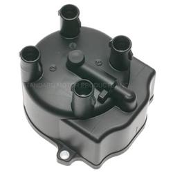
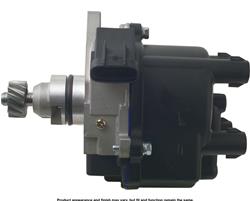


    The "internal coil" will have to be removed and a new connection made to the cap in order to hook a coil wire between the cap and an external coil. This will require some fabrication of new parts.

    Comment


    • Originally posted by Gary Hammond View Post
      Hi Aaron,


      We must have both been posting at the same time. I didn't see your post until after mine appeared in the thread.

      I understand what you're saying and acknowledge that you're correct. But the distributor on Ron's vehicle is different than most others, in that it has no external coil to rotor wire to hook up an external coil! It has a "built in coil" under the distributor cap. Is that how yours is as well? Here's a couple of photos of the system Ron must have.


      The "internal coil" will have to be removed and a new connection made to the cap in order to hook a coil wire between the cap and an external coil. This will require some fabrication of new parts.
      Yes, that is my distributor. I modified the cap with a connector in the center to connect the external coil to the rotor and I disconnected the internal coil wires to connect to the external coil and MSD unit.

      Comment


      • Originally posted by rokan View Post
        Originally I had the small red wire going to the ignition and had the problem so I switched it just to try but it made no difference? But the other wires may be wrong like you say? The way I had it wired originally was the way the guy at MSD told me to do it but he may not have completely understood what my ignition actually is? I will try rewiring it like you say Aaron and see if that makes any difference.

        Thanks,
        Ron
        That is interesting MSD would say that because no matter the ignition, the small wire will always be the power switch wire no matter what. When 12+ positive goes to the small red wire, then the large red wire going to the battery is then connected to the circuit inside - probably thru some solid state relay or similar.
        Aaron Murakami


        You never change things by fighting the existing reality. To change something, build a new model that makes the existing model obsolete.” ― Richard Buckminster Fuller

        Comment


        • Originally posted by Richard View Post
          MSD says "Solid core spark plug wires cannot be used with the 5520".
          Aaron, will this interfere with our Plasma Ignition work?
          Don't you recommend solid core wire for best performance with the Plasma Ignition?
          Thanks.

          Richard Gieser
          The cables aren't that important for the plasma itself since the cap discharges across the spark plug gap and not through the entire cable.

          However, since this method of plasma ignition is initiated with a CDI spark, it is a good idea to have cables that are suited for capacitive discharge.
          Aaron Murakami


          You never change things by fighting the existing reality. To change something, build a new model that makes the existing model obsolete.” ― Richard Buckminster Fuller

          Comment


          • Originally posted by Gary Hammond View Post
            Hi Aaron,


            We must have both been posting at the same time. I didn't see your post until after mine appeared in the thread.

            I understand what you're saying and acknowledge that you're correct. But the distributor on Ron's vehicle is different than most others, in that it has no external coil to rotor wire to hook up an external coil! It has a "built in coil" under the distributor cap. Is that how yours is as well? Here's a couple of photos of the system Ron must have.


            The "internal coil" will have to be removed and a new connection made to the cap in order to hook a coil wire between the cap and an external coil. This will require some fabrication of new parts.
            Ok, that's interesting - haven't seen that before. Didn't know what the multiple references were to the coil in the distributor. I wonder if they make aftermarket versions of these with coils that are intended be used with cap discharge.

            Just saw Ron's post.
            Aaron Murakami


            You never change things by fighting the existing reality. To change something, build a new model that makes the existing model obsolete.” ― Richard Buckminster Fuller

            Comment


            • Hi Ron,

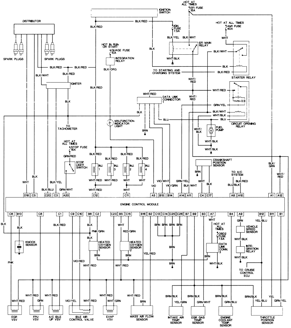
              I found a wiring diagram that claims to be for your vehicle. Maybe with Aaron's help, you can figure out how to wire everything up so it will work.

              Comment


              • Awesome! Thank you for the schematic!
                Here are some pics of the inside of my distributor.
                Aaron,
                I tried wiring it like you said and it won't start that way? Maybe I didn't do it quite right, I dunno?? One of tbhe problems is the distributor connector has the 2 magnetic pickup lead wires and the 2 coil wires going thru it. Do they somehow need to feed back to the computer??
                Thanks,
                Ron
                Attached Files
                Last edited by rokan; 09-01-2018, 05:40 PM.

                Comment


                • Hi Ron,

                  Originally posted by rokan View Post
                  Awesome! Thank you for the schematic!
                  Here are some pics of the inside of my distributor.
                  Aaron,
                  I tried wiring it like you said and it won't start that way? Maybe I didn't do it quite right, I dunno?? One of tbhe problems is the distributor connector has the 2 magnetic pickup lead wires and the 2 coil wires going thru it. Do they somehow need to feed back to the computer??
                  Thanks,
                  Ron
                  According to the schematic two wires (the solid black and the solid white wires in the schematic) connect the two magnetic pickup wires inside the distributor (yellow wire and green wire in photo) and go from the connector directly to the computer.

                  The other two wires that go thru the connector, go to the primary winding of the coil. The black w/ red tracer wire is a 12 volt (+) lead from the ignition switch to the positive side of the coil primary and also supplies 12 volts (+) to the igniter. The black wire w/ white tracer goes to the igniter and would be the momentary ground (-) connection for the coil every time the computer tells the igniter to fire (just like a set of points and condenser would). The igniter gets it's signal from the black wire w/ blue tracer and black wire w/ yellow tracer coming from the computer to the igniter.

                  It appears to me that you have two options with this setup. One is to rewire the stock coil to work with the MSD module, and the other option is to completely remove the stock coil and use the Nology ProFire coil you purchased. Either way the igniter will have to be bypassed and it's trigger signal from the computer also applied to the MSD module. I don't think the igniter can be completely removed, because it also is connected to the tachometer, the heated oxygen sensor, and data link connecter.

                  Let me know which option you want to use and I'll help you figure out the connections to do it.

                  Comment


                  • Originally posted by Gary Hammond View Post
                    Hi Ron,


                    According to the schematic two wires (the solid black and the solid white wires in the schematic) connect the two magnetic pickup wires inside the distributor (yellow wire and green wire in photo) and go from the connector directly to the computer.

                    The other two wires that go thru the connector, go to the primary winding of the coil. The black w/ red tracer wire is a 12 volt (+) lead from the ignition switch to the positive side of the coil primary and also supplies 12 volts (+) to the igniter. The black wire w/ white tracer goes to the igniter and would be the momentary ground (-) connection for the coil every time the computer tells the igniter to fire (just like a set of points and condenser would). The igniter gets it's signal from the black wire w/ blue tracer and black wire w/ yellow tracer coming from the computer to the igniter.

                    It appears to me that you have two options with this setup. One is to rewire the stock coil to work with the MSD module, and the other option is to completely remove the stock coil and use the Nology ProFire coil you purchased. Either way the igniter will have to be bypassed and it's trigger signal from the computer also applied to the MSD module. I don't think the igniter can be completely removed, because it also is connected to the tachometer, the heated oxygen sensor, and data link connecter.

                    Let me know which option you want to use and I'll help you figure out the connections to do it.
                    What is the red wire from the + of the coil to the back of the magnetic pickup in the pics?
                    Aaron Murakami


                    You never change things by fighting the existing reality. To change something, build a new model that makes the existing model obsolete.” ― Richard Buckminster Fuller

                    Comment


                    • Hi Aaron,

                      Originally posted by Aaron Murakami View Post
                      What is the red wire from the + of the coil to the back of the magnetic pickup in the pics?
                      I didn't see that at first glance and was wondering about it after my last post. I suspect it provides 12 volts (+) to the magnetic pickup since it fastens to the coil (+) terminal along with the wire coming from the ignition switch. This complicates matters as the magnetic pickup will still need 12 volts (+) on this lead to trigger the computer. But the coil has to be separated and driven only by the MSD orange and black wires.

                      In order to retain and use the stock coil, a new (fifth) lead will have to enter somewhere other than thru the existing connector which has only four leads. (Can't use lead sharing when driving the coil with the MSD.)

                      If the external coil is used then the original coil must be disconnected or removed (and replaced with some type of filler block shaped like the coil) and the lead from the ignition switch then connected directly to the red wire you asked about going to the magnetic pickup. If the coil is only disconnected and left in place as a filler block, the secondary terminal will need to be removed and well insulated from it's original contact with the cap.

                      This is not an easy vehicle to modify, but I think it can be done.

                      Comment


                      • Originally posted by Gary Hammond View Post
                        Hi Aaron,


                        I didn't see that at first glance and was wondering about it after my last post. I suspect it provides 12 volts (+) to the magnetic pickup since it fastens to the coil (+) terminal along with the wire coming from the ignition switch. This complicates matters as the magnetic pickup will still need 12 volts (+) on this lead to trigger the computer. But the coil has to be separated and driven only by the MSD orange and black wires.

                        In order to retain and use the stock coil, a new (fifth) lead will have to enter somewhere other than thru the existing connector which has only four leads. (Can't use lead sharing when driving the coil with the MSD.)

                        If the external coil is used then the original coil must be disconnected or removed (and replaced with some type of filler block shaped like the coil) and the lead from the ignition switch then connected directly to the red wire you asked about going to the magnetic pickup. If the coil is only disconnected and left in place as a filler block, the secondary terminal will need to be removed and well insulated from it's original contact with the cap.

                        This is not an easy vehicle to modify, but I think it can be done.
                        I think we need to leave the igniter in the circuit for the computer to operate properly??
                        If we could make the stock coil work that will be fine but I already have it bypassed and am using the Nology coil now. I currently have the 2 coil wires coming out of the distributor that I have connected to my MSD unit, again with the white wire connected to the - wire of the stock coil to get my engine to run at this time.
                        I have already modified the cap to separate the internal coil from the center post plus both wires have been disconnected form the internal coil.

                        Comment


                        • That little red wire goes to a condenser set down into the distributor housing

                          Comment


                          • Hi Ron,

                            Originally posted by rokan View Post
                            I think we need to leave the igniter in the circuit for the computer to operate properly?? ........................................
                            I don't think the igniter can be completely removed, because it also is connected to the tachometer, the heated oxygen sensor, and data link connector.

                            I currently have the 2 coil wires coming out of the distributor that I have connected to my MSD unit, again with the white wire connected to the - wire of the stock coil to get my engine to run at this time.
                            I don't fully understand what you just explained. The two "coil wires" coming out of the distributor ----- are these the wires connected to the yellow and green wires inside the distributor? If so, this would be the white and black trigger signal wires that go to the computer (these should hook only to the computer)? Or do you mean the two wires from the igniter that originally hooked to the internal coil (black w/red tracer and black w/white tracer)? What wires from the MSD unit are hooked to these?

                            again with the white wire connected to the - wire of the stock coil to get my engine to run at this time.
                            The white wire ------is this the white wire from the MSD box that is supposed to be used with breaker points? If so, this is what's triggering the MSD box and is getting it's signal from the igniter and should work. The igniter mimics a point and condenser set and is controlled by the computer.

                            I assume you have the orange wire and black wire from the MSD unit connected to the Nology coil primary terminals, correct?

                            Comment


                            • Originally posted by rokan View Post
                              That little red wire goes to a condenser set down into the distributor housing
                              My best guess is the condenser was probably there to help filter out back spikes from the original coil and prevent them from messing with the magnetic pickup.

                              Comment


                              • Originally posted by Gary Hammond View Post
                                Hi Ron,


                                I don't think the igniter can be completely removed, because it also is connected to the tachometer, the heated oxygen sensor, and data link connector.


                                I don't fully understand what you just explained. The two "coil wires" coming out of the distributor ----- are these the wires connected to the yellow and green wires inside the distributor? If so, this would be the white and black trigger signal wires that go to the computer (these should hook only to the computer)? Or do you mean the two wires from the igniter that originally hooked to the internal coil (black w/red tracer and black w/white tracer)? What wires from the MSD unit are hooked to these?


                                The white wire ------is this the white wire from the MSD box that is supposed to be used with breaker points? If so, this is what's triggering the MSD box and is getting it's signal from the igniter and should work. The igniter mimics a point and condenser set and is controlled by the computer.

                                I assume you have the orange wire and black wire from the MSD unit connected to the Nology coil primary terminals, correct?
                                The two coil wires do not connect to the yellow and green magnetic pickup wires and Yes the two coil wires that come from the igniter that go inside the distributor and attach to the original coil, the white MSD wire connects to the negative wire of the internal coil wires and that white wire is for points or electronic ignition amplifier from what the MSD instructions say
                                And yes, I do have the orange and black MSD wires connected to the Nology coil

                                Theoretically it should work BUT whenever I connect anything to the T junction of my spark plug wire so as to ad the plasma spark to it the engine completely misfires!? And that is only connecting 1 wire to #1 spark plug even when NOTHING is connected to the other end of that wire???

                                Comment

                                Working...
                                X