Announcement

Collapse
No announcement yet.

What's the best cap dump circuit?

Collapse
X
 
  • Filter
  • Time
  • Show
Clear All
new posts

  • RS_
    replied
    Mikey,

    4uA supply current, but will pull what ever mA that it takes to drive the H11D1 LED when triggered...... http://www.maximintegrated.com/datas...ex.mvp/id/1219

    "Hysteresis reset point adjust" lets you adjust the reset point so that the discharge stops where you want it, for example, 2V over the charging battery V when fully charged.....
    so that it will self adjust to being 2V over the charging battery V, on a run down battery......

    Went through inventory and pricing hell for 5 mo..... Have lost all focus, and have not done a damn thing on Bedini or Aquaponics projects since the fire...... as all the important Bedini projects and equipment, and my PVC inventory, tools, etc... were destroyed......
    waiting on insurance to finalize......... so i can rebuild and replace tools and other things
    Last edited by RS_; 10-06-2013, 02:05 PM.

    Leave a comment:


  • RS_
    replied
    compairtor with reset point adjust

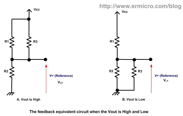
    this is my comparator circuit with reset point adjust.....

    it is reverse input on the opamp from what JB's comparator circuit is...... this allows the Hysteresis reset point adjust to work correctly........

    the MAX931 is a very Low power comparator, and can be used in less than 12V circuits, like SG oscillators run from a Crystal battery to charge the capture cap...

    as always, the values may need to be tweaked for your system.....
    i have a couple of versions of this circuit running with small differences between them.....

    for 12 V systems or less, will NOT Work in 24V battery charge systems

    JB has not approved this circuit, so i will take it down if he does not approve of it.........

    PS: Ignore the lines coming off of the top of C2, an the line off the output of the comparator, and going off page to the left.......
    Attached Files
    Last edited by RS_; 10-06-2013, 11:08 AM.

    Leave a comment:


  • Tom C
    replied
    forelle, learning is half the fun!! figure it out it will be a huge aha moment Electronics Components: How to Use an Op Amp as a Voltage Comparator - For Dummies and http://cornerstonerobotics.org/curri...omparators.pdf and

    Leave a comment:


  • James Milner
    replied
    Forelle,
    The circuit diagram from RS deals with the peak dump voltage but not the voltage it drops to.
    The only other answer I can give you is to play with the comparitor circuit hysteresis, but it will not give you accurate low end discharge voltage.
    I hope John does answer. That being said John is POTTING the large comparitor that is sold through Teslagenx. This is so you can't see it! John has been ever so generous already! The amount of information and guidance personally and through Tom, John and Erik is more than anyone could ever hope for! Sadly you will not receive a circuit on a platter! Just like the rest of us you will need to experiment with multiple options until you get it to a point you are happy to leave it as it is and focus on tweaking another part of the system. That is until someone else posts another little gem or John produces another video or handbook. I believe another is due at the end of the year for advanced builds. Aaron you may wish to post an update here? You never know you might strike it lucky then?

    Leave a comment:


  • forelle
    replied
    Originally posted by James Milner View Post
    Forelle,
    I think you are looking more at a window comparator. Which uses two comparators. One to detect the high and one to detect the low. Then feed the appropriate signals to a triggering transistor or relay for the FETs. Thanks Tom for mentioning about matching. I had failed mention it in my last post but do it as a matter of routine these days. I have not gone down the window comparitor path due to time restrictions and finding the current circuit adequate. Now that what you are seeking is becoming clearer it's only a matter of time before someone comes up with a circuit.
    Forelle, if you have the time you can google some good info on the subject. It may help you develop a circuit yourself. It's a great way to learn!
    I hope that is a small help. I'd have a go myself but am so time poor at present.
    Don't give up seeking the way forward.
    James
    Hi James
    This sounds to me that the Bedini comparator /Ferriswheel circuit is not capeable of setting the voltage at the end of the dump.What i could not realy believe.I know this circuit with 2 OP Amp from Diverfun one site back and i know that there is much info on the net,but why should i develope a circuit by myself when i can take one from John Bedini.
    Maybe we have luck and he is reading this post.I am sure with some few words he can help us,i am sure i am not the only one who want to know how its working.
    Thanks

    Leave a comment:


  • hobbyrobotik
    replied
    bonjour intactsaphir,

    find better image on my webspace:


    BUT circiut works only with capacity lower than ~2500 micro Farad (charging batteries 2...5AH)

    have fun

    Leave a comment:


  • James Milner
    replied
    Forelle,
    I think you are looking more at a window comparator. Which uses two comparators. One to detect the high and one to detect the low. Then feed the appropriate signals to a triggering transistor or relay for the FETs. Thanks Tom for mentioning about matching. I had failed mention it in my last post but do it as a matter of routine these days. I have not gone down the window comparitor path due to time restrictions and finding the current circuit adequate. Now that what you are seeking is becoming clearer it's only a matter of time before someone comes up with a circuit.
    Forelle, if you have the time you can google some good info on the subject. It may help you develop a circuit yourself. It's a great way to learn!
    I hope that is a small help. I'd have a go myself but am so time poor at present.
    Don't give up seeking the way forward.
    James

    Leave a comment:


  • forelle
    replied
    Originally posted by BroMikey
    Fets, caps, sizing whatever it is you are trying to do the question was "How do I control dump Voltage"???

    That was the question, NO?

    Yes it was the question.

    You could use a computer to do it OR you could use a simple 555 timer as I have shown and yes the 555 time IS a comparator.

    I will repeat it again for you engineering students, a 555 timer is a comparator based chip.

    Comparator is a broad term or idea.

    Anyone with a 555 timer can be dumping TODAY and stopping dump voltage ANYWHERE THEY WANT today.

    From here we need to know if you are planning to cap dump a 2 ah battery or a 2000ah battery.

    Or if we are talking learning new things.

    If you are just strictly on a learning spree, I find no fault in that, however if you honestly wanted to charge a battery with a circuit that controls dump down voltage (THIS MONTH) I don't see the big problem.

    Have fun looking for a circuit that is ready.

    Oh yes that was your other challenge that no where on the forum was there a circuit to do this.

    See what I mean? You stated that you could not find such a circuit and now that you have found it what will you do with it?

    Wasn't that your original beef about finding a working circuit?

    15,000uf is find for a 10ah battery.

    A single car battery might charge up in a day or so, very small circuit.

    Yes larger fets or arrays of transistors could be used and as I said you could use a microprocessor controlled dump.

    But that was not your question was it?

    Dump down voltage is controlled using a simple diode and pot. This is the fast way til you might us a Zener, but then you are struck with a single set voltage.

    Unless you make more circuits that have switches for 12v, 24v, 36v or in between.

    Mean while one diode later with a small pot you can do the same thing but you will have any voltage, like JB sells.

    Thanks for hearing me out.Great going men onward.


    Mikey
    The question was how do i set the voltage at the end of the dump by the circuit from Ron Chase/Bedini Comparator circuit.Of course ,i can build the circuit with the 555 Timer but what shall i do with my circuit with the OP Amp?I dont want to dismantle it.Especially because there is only 1 or 2 parts to change that its working.If i would have known that this circuit is not ready to be rebuild,i wouldn't take it.I tought there are many people on this forum who are familiar with electronics and know how to adjust a simple comparator,but it looks like i am wrong.
    So my last chance before i beginn to study electronics by myself is to ask John Bedini,Hello John,can you tell me how to set the voltage at the end of the dump by your comparator circuit from the Ferris Wheel?
    Thanks a lot

    Leave a comment:


  • Tom C
    replied
    Hey guys, FET's are just like transistors in that they need to be matched, so the gates need to be matched so they all switch on the same amount. if you dont then you may have one fet handling most of the current, and you are losing out on the gains by adding fets and lowering resistance.
    Tom C

    Leave a comment:


  • forelle
    replied
    Originally posted by James Milner View Post
    Forelle,
    I've played a little with this and you can improve your discharge by increasing the number of FETs you use when you dump. I started at two (discharged about 3v)went to four (discharged about 5-6v) and now shortly to try 6. I noticed John used 5!
    Remember as you add more fets it's like adding resistors in parallel. You reduce the overall resistance thereby increasing current flow and an ability to shift more joules faster.
    We don't need to set a lower limit as it will naturally discharge all the way to the charge battery voltage given the right conditions. We want to use a fire hose rather than a straw
    The FETs are the first bottleneck.
    The capacitors are the second!

    Getting lower ESR caps can increase the rate of discharge as well. LOW ESR caps are usually taller than regular capacitors. I use 6 regular caps ( because that's all I have ) in parallel each at 10,000uF rated at 100v. Using more smaller caps in parallel can help lower your combined apparent ESR if you can afford the caps that cost $60 a piece (for a total of 60,000uF or thereabouts ).

    By the way the total capacitance of your cap dump will affect the rate at which you can reach your preset voltage and dump. So if you use only 20,000uF then you will dump at a faster time interval than say 60,000uF in fact about 3 x faster!

    In case you are interested I used Ron Chase's comparitor cap dump circuit (Thanks Ron!) easily found on the forum but modded it to have 4 FETs dump at one time and now I've stepped up to 6. Thats all there is to it. Someone else may have a another way, even a better way, but as they say there are many ways to skin a cat!
    When I currently dump with 4 FETs I dump at 24 and cut off at about 16-17v.
    I can tell you it works a treat!
    James
    I talk about the same circuit you build and i used 7 Fets right away,to you used the same parts as suggested?

    Leave a comment:


  • forelle
    replied
    Originally posted by BroMikey
    Hi guy type in "capacitor discharging" well here I did it for http://www.energyscienceforum.com/jo...ing-units.html

    [ATTACH=CONFIG]2698[/ATTACH]
    So what a about it? U gonna build it?

    Mike
    I beginn with the comparator circuit from Ron Chase/ Bedini Ferriswheel and i would like to finish it.
    Thanks for your suggestion.

    Leave a comment:


  • James Milner
    replied
    Forelle,
    I've played a little with this and you can improve your discharge by increasing the number of FETs you use when you dump. I started at two (discharged about 3v)went to four (discharged about 5-6v) and now shortly to try 6. I noticed John used 5!
    Remember as you add more fets it's like adding resistors in parallel. You reduce the overall resistance thereby increasing current flow and an ability to shift more joules faster.
    We don't need to set a lower limit as it will naturally discharge all the way to the charge battery voltage given the right conditions. We want to use a fire hose rather than a straw
    The FETs are the first bottleneck.
    The capacitors are the second!

    Getting lower ESR caps can increase the rate of discharge as well. LOW ESR caps are usually taller than regular capacitors. I use 6 regular caps ( because that's all I have ) in parallel each at 10,000uF rated at 100v. Using more smaller caps in parallel can help lower your combined apparent ESR if you can afford the caps that cost $60 a piece (for a total of 60,000uF or thereabouts ).

    By the way the total capacitance of your cap dump will affect the rate at which you can reach your preset voltage and dump. So if you use only 20,000uF then you will dump at a faster time interval than say 60,000uF in fact about 3 x faster!

    In case you are interested I used Ron Chase's comparitor cap dump circuit (Thanks Ron!) easily found on the forum but modded it to have 4 FETs dump at one time and now I've stepped up to 6. Thats all there is to it. Someone else may have a another way, even a better way, but as they say there are many ways to skin a cat!
    When I currently dump with 4 FETs I dump at 24 and cut off at about 16-17v.
    I can tell you it works a treat!
    James
    Last edited by James Milner; 10-05-2013, 06:47 AM. Reason: Attempting to fix my bad grammar and expand on detail

    Leave a comment:


  • forelle
    replied
    Originally posted by forelle View Post
    Hi All,
    I have the same question,because i have only 4V difference,eg. from 24V down to 20V,or from 30V down to 26V.
    Thanks
    How can you set the voltage at the end of the dump.
    Is there nobody who knows how to do this.
    Why is in this Forum not a single Cap dump circuit wich is working like it should for a bicycle wheel,that charge to 25V and dump to 17V.There are so many Threads about cap dump.For me its very strange whats going on here.I speak about comparator not 555 timer.
    Last edited by forelle; 10-05-2013, 12:38 AM.

    Leave a comment:


  • intactsaphir
    replied
    hello hobbyrobotik. Is it possible to increase the resolution of your picture? He texts that I do not see.
    thank you

    bonjour hobbyrobotik. Serait il possible d'augmenter la resolution de ton dessin? Il a des textes que je ne vois pas.
    Merci.

    Leave a comment:


  • guyzzemf
    replied
    this is a good vid on the comparator

    The SG Energizer Cap Dump John Bedini & Chuck Hupp - YouTube

    guyzzemf

    Leave a comment:

Working...
X