Hello bmeheboob
my suggest is to power your circuit using 12v car battery followed an inverter (often suggested is sine wave type)
Next power your device from there on. Of course send some energy back to the battery too.
You may find following pdf useful:
http://frienergi.alternativkanalen.com/Smith.pdf
Good luck.
Lightworker2
-
Hello macitana
I see you post is a recent one. My question is Petio still active on this forum?
I also see you presented a circuit. Have built any device using it?
I have a high voltage unit that I built some time back.
Here is a video of that too
https://youtu.be/Jf7SpoR2ic4
This unit is running 7,500 Volts. Red wire insulation upto 30kV DC
Thanks
Lightworker2Last edited by Lightworker2; 02-12-2019, 03:16 PM.Leave a comment:
-
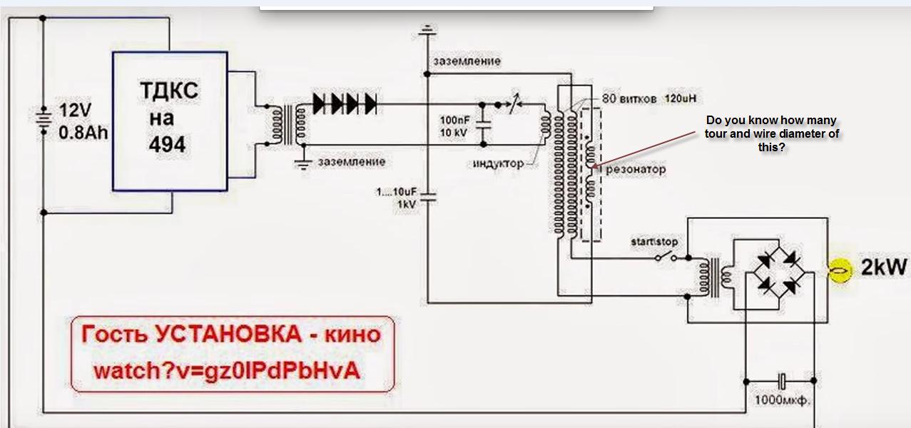
Hello Petio707, here for convenience have uploaded your original image.
Lightworker2Leave a comment:
-
Hello petio707,
In Patrick Kelly's booklet, PJKbook.pdf page 103,
the Donald Smith type of device that does not use a capacitors but only spark-gap and coils L1 and L2 uses following strategy:
Start by making the L2 coil wire length exactly four times the length of L1 coil, and make sure cutting the lengths accurately.
It is common practice to match the weight of copper in each coil and so the shorter wire is usually twice the diameter of the
longer wire.
Your Kappa Coil is configured as 20T CCW, 80-120T CW, 6T CCW.
Right away we see, L2 is about four times the length of L1.
I think resonance does play a part since it does require tweaking L1 or L2 coil turns. The L3 coil I also think probably follows the same length/weight principle.
In earlier days, Kapanaza did say, I think, that he studied Don Smith circuits before making his.
Lightworker2Leave a comment:
-
Hello petio707, I on this thread. see your point. Examining the picture of your kapagen coil, I see that you have presented 20T CCW, 80-120T CW, 6T CCW. In LCR circuit. If you say it is not resonance then number of turns are not very critical. We know resonance is very sensitive to number of turns in a coil. Once some Russian guy made statement that if 2nd coil becomes resonant then you will have opportunity to recover your original input power. If there was 3rd coil also in resonant state, then this third coil will produce more output power than input power. I at present do not know that this is a fact. Also Donald Smith in one of his devices was telling that one central coil when surrounded number of secondary resonant coils then the system will produce many more copies of greater power output. I have no proof of this concept either. Good luck.Leave a comment:
-
Hello petio707
I am returning member to these forums. I have tried building similar system some years ago. I think I will try replicating your system.
regardsLeave a comment:
-
Hi Tom C ,Originally posted by Tom C View Post
The link you suggested us to read is in some kind of the system Tesla experimented with to produce his Radiant system (this Uses AC and DC both)... Now i'dont just understand why the hell is the main stream making this a Complex study...Radiant Burst oh sorry...... Reactive Power is messed upon as being considered purely Transverse in Nature..how misleading..god save Engineers who shall ponder aimless on this well established Science for years to come....
Rgds,
Faraday88.Leave a comment:
-
Hi bmeheboob,
You have to try a combination without M.O.B.Try a new one with a flyback and 9-12 v.Leave a comment:
-
Hi Petio,
I have replicated the Kapanadze generator and I am getting an output of 2KW almost. I am getting output only till and whenever there is an Input supply (to Transformer). I have made the exact as circuit mentioned above.
But How do we make it free energy device.. Could you help me. Thanks in advanceLeave a comment:
-
Hi Petio,
I have replicated the Kapanaze and I am getting an output of 2KW almost. I am getting output only till and whenever there is an Input supply (to Transformer). I have made the exact as circuit mentioned above.
But How do we make it free energy device.. Could you help me. Thanks in advanceLeave a comment:
-
until we can understand the output of the device we will not understand how to help and give some specifications of the components you may need. if it is A.C. a transformer to step the voltage up or down will work. if it is D.C. then a battery bank to store its energy is the next step, but how to interface the unit is still a mystery.
Tom CLeave a comment:
-
sorry for the really late reply...Originally posted by Botster View Post
http://electricsaver1200.com/blog/po...-power-saving/
http://www.schneider-electric.co.uk/...n-modules.page
http://www.eaton.com/Eaton/ProductsS...tion/index.htm
Tom C
Leave a comment:
-
I can't measured the output, it's very unstable, not sinus ac... and my 1000V graetz bridge was go wrong. So I think it's more higher than 1000V, perhaps 2kV.
Now I bought 6kV diodes and it must be enough strong.Leave a comment:
Leave a comment: