Originally posted by elmar
View Post
I re-watched and must have misunderstood him the first time, he is talking about 4 phases not 4 switchings.

"you're seeing this phase, then this phase, then this phase, then this phase." He points to the LED's one at a time.
so somehow it would seem he is does have the genny coil feeding back into the system.
what we know:
1. two coils at 90 degrees
2. drive coil 2 winds/filer 900 turns smaller gauge
3. genny coil also 2 winds/filer 300 turns larger gauge
4. 4 LED's one for each "phase"
5. carbon graphite ball
6. aluminium cylinder with fan to show work adjust speed who knows what else.
7. Basic SSG circuit
I wonder if he is using a switching diode somehow to put the energy back to the source as the original simplified school girl circuit did?
-Patrick
 has a momentum on its own. He says aluminium can be magnetic, this has to do with the radiant field the motor generates, and the cylinder gets part of its spin from it. That´s why the axis of the Al cylinder is movable so that it can be arranged for the right resonance. He pointed out that the green LED or Neon lamps (I don´t know what lamps he used) function like a tesla switch. In fact, I see no wires attached to them. (all said IMHO).
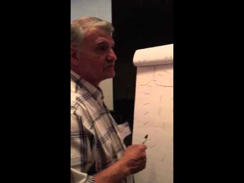
Leave a comment: