 Tweet
Tweet
Hallo,
I am not an expert on electronics ( I am learning) but I managed anyway to build my Bedini SSG, it is running perfectly rejuvenating batteries without problems.
Bike wheel diam. 63,5 cm
21 Magnets 5x2,5x1cm (smaller than indicated on the book but in EU could not find them)
Coil: Teslagenx 7 strand + 1
RPM 314
Amp in 1,4
Amp out 0,6-0,7
Batteries (Primary and Charge) 12V - 45ah
Resistence on impulse 157 Ohm (Potentiometer stil there)
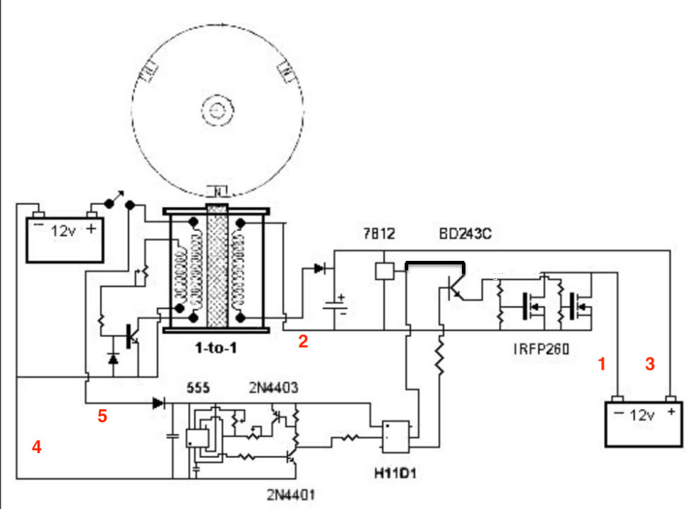
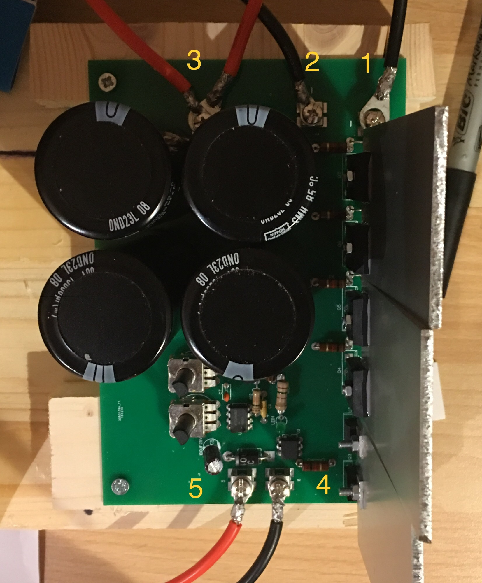
I wish to add the Cap Dump but, I am having difficulties on understanding the right connections for the Cap Module I tried to build...
I post here the images of circuit, PCB and schematic:
When I connected 1 to the neg charging Battery and 2 to the pos it fried the ammeter immediately.
What am I doing wrong ?
Some help would MUCH appreciated..…
thank you
regards
claudio

I am not an expert on electronics ( I am learning) but I managed anyway to build my Bedini SSG, it is running perfectly rejuvenating batteries without problems.
Bike wheel diam. 63,5 cm
21 Magnets 5x2,5x1cm (smaller than indicated on the book but in EU could not find them)
Coil: Teslagenx 7 strand + 1
RPM 314
Amp in 1,4
Amp out 0,6-0,7
Batteries (Primary and Charge) 12V - 45ah
Resistence on impulse 157 Ohm (Potentiometer stil there)
I wish to add the Cap Dump but, I am having difficulties on understanding the right connections for the Cap Module I tried to build...
I post here the images of circuit, PCB and schematic:
When I connected 1 to the neg charging Battery and 2 to the pos it fried the ammeter immediately.
What am I doing wrong ?
Some help would MUCH appreciated..…
thank you
regards
claudio


 This is normal, but a little spooky if you're not looking for it. This is only momentary as you can tell if you disconnect and then reconnect.

Comment