Announcement

Collapse
No announcement yet.

The Toy Build

Collapse
X
 
  • Filter
  • Time
  • Show
Clear All
new posts

  • The Toy Build

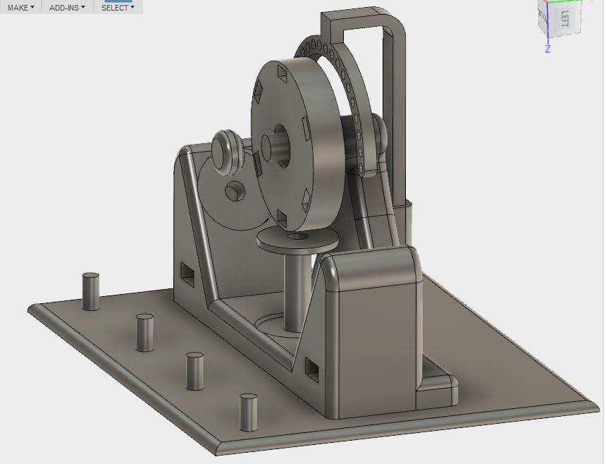
    This is a very small build I am calling "The Toy".

    It is another 3D print model but simplified even more than the first one I posted. The parts for this are very minimal intentionally. It is very small having only a 50mm wheel. The deck is approximately 5 3/4 X 4 3/4 inch.

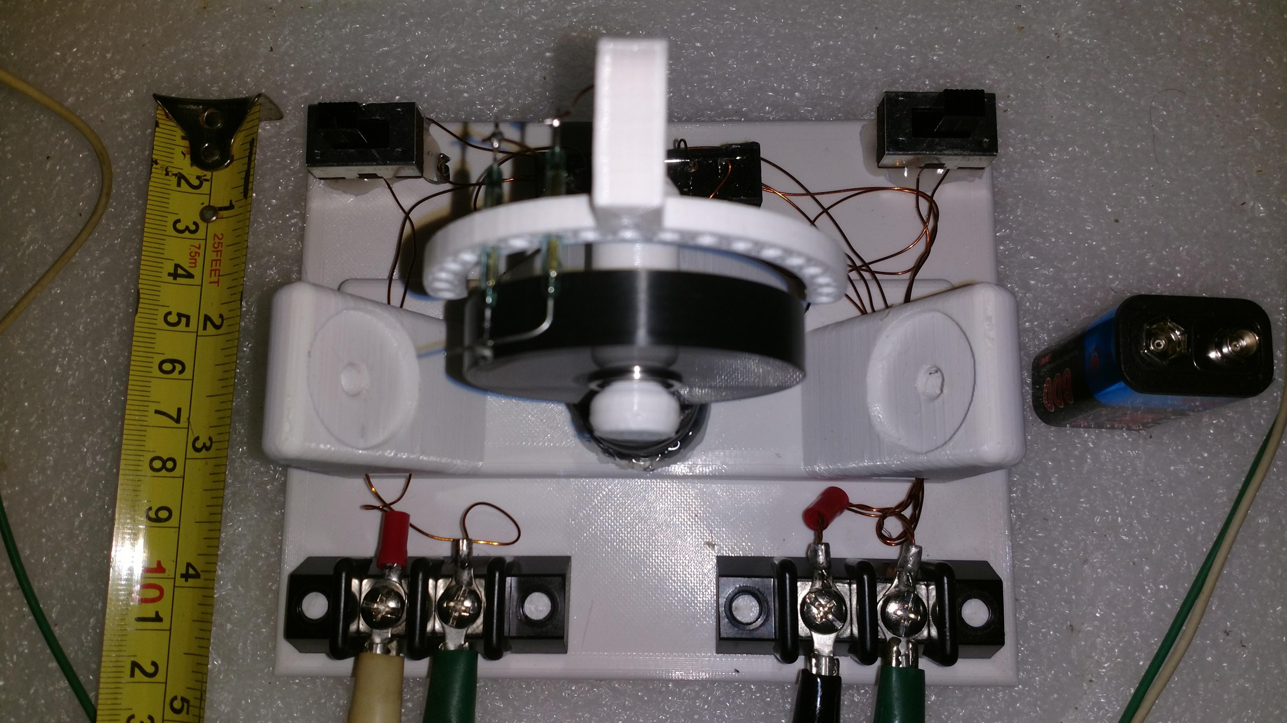
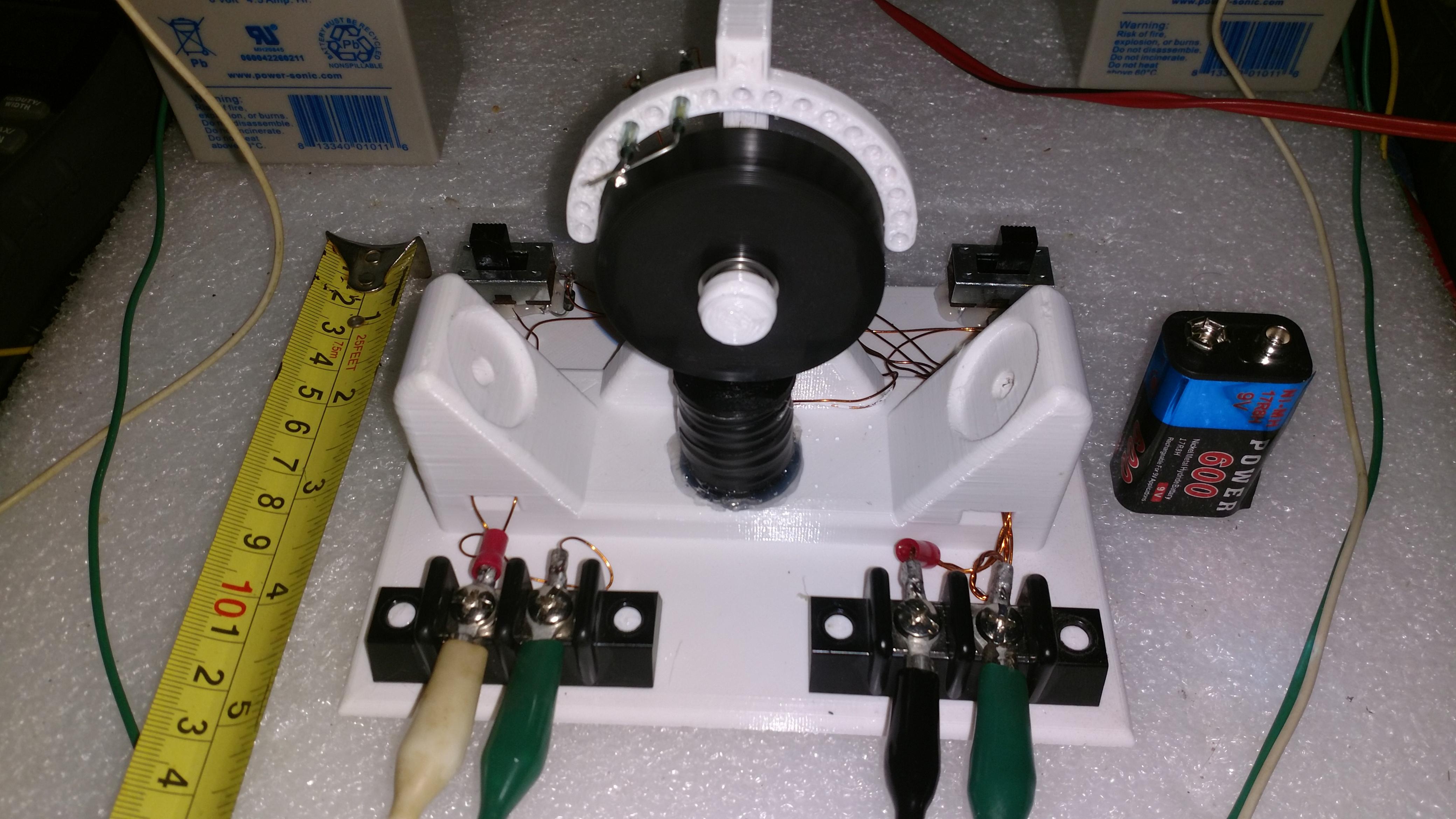
    I have only run it a short time so far because I just finished building it last night but so far it works nicely. In mode one it is pulling about 150ma at 6V and around 300ma $ 6volt for common ground mode. I still need to do a lot of testing at different voltages but I started on the 6 volts 5AH that I have. I think it would run fine on soe 18650's or similar as well.

    Anyway I will post some build files once I have tested a bit more with it.

    Click image for larger version

Name:	BZ-Toy Bottom.JPG
Views:	1
Size:	52.2 KB
ID:	51403

    Click image for larger version

Name:	BZ-Toy Angle.JPG
Views:	1
Size:	54.4 KB
ID:	51404

    Click image for larger version

Name:	BZ-Toy LEFT.JPG
Views:	1
Size:	33.0 KB
ID:	51405

    Click image for larger version

Name:	BZ-Toy-1.jpg
Views:	1
Size:	796.7 KB
ID:	51406

    Click image for larger version

Name:	BZ-Toy-2.jpg
Views:	1
Size:	736.1 KB
ID:	51407

  • #2
    Hi Bob,

    That looks pretty neat! And just in case you missed it, I sent you a PM.

    Comment


    • #3
      Bob,

      the trigger bracket is awesome!!

      Tom C


      experimental Kits, chargers and solar trackers

      Comment


      • #4
        Thanks guys.

        I wired this one up with a small SSR but I am also going to try a BJT build on this platform.

        Gary I just checked and there was no message from you, don't know what could have happened. Can you send again?

        Comment


        • #5
          Very cool Bob, keep up the great ideas.

          Comment


          • #6
            Hi Bob,

            I re-sent the message.

            Originally posted by BobZilla View Post
            Thanks guys. ...............
            Gary I just checked and there was no message from you, don't know what could have happened. Can you send again?

            Comment


            • #7
              I made a slight improvement the base piece. Previously I had posts there for mounting store bought terminal blocks but I created terminal blocks on the model instead. These will work by slipping a square nut into the slot and then using a #8 screw and washers on top. Saves about 10 dollars on parts.

              Also in this shot you can see better how the axle is desighned. It is not one piece with the base. Originally I did have it all one piece but in printing it the supports were terrible and the roundness of it was not as nice. It is a separate part that should be printed at 90 degrees so that no supports are needed and teh printer can make a nice circle, then it has a plug to fit into the base.

              Click image for larger version

Name:	BZ-Toy Base.JPG
Views:	1
Size:	59.8 KB
ID:	49581

              Comment


              • #8
                Originally posted by Richard
                Nice terminal arrangement, Bob.
                Now we just gotta find those square electrical washers that are so common with terminal strips but I've never seen them available for purchase separately.
                I thought so at first too but with how I am doing this you don't need them. The square nut anchors the screw as you tighten it and with two washers up top you can sandwich a ring terminal between and have a tight connection.

                Here is a pic of one I actually printed:
                Click image for larger version

Name:	BZ-Toy Base_2.jpg
Views:	1
Size:	389.0 KB
ID:	49583

                Comment


                • #9
                  Awesome work Bob. Thanks for sharing.

                  Looks like you've got 3D printing down pat

                  John K.

                  Comment


                  • #10
                    Thanks John. Yea I m getting the hang of it. For everything you see there are probably 40 versions leading up to it, not major changes but little changes here and there.

                    So here is a little update on this build. I have made a BJT driven version of it but it was not without it's problems. Over all I think this machine is worth pursuing further so I am going to try some adjustments and see if it gets better but as it is I don't think it's worth putting out for others to replicate if they want too. Unlike my other machine this one is just not top quality, at least not yet.

                    So I rolled a coil with a trigger (30awg) and a power (24awg) on the same spool in the traditional manor except not litz'ed. My thought was to have the trigger coil on the right, a slave on the left and keep the middle for a genny which is why I put that 3rd terminal block in the middle. Well I could not get enough current or voltage ( not sure which) to fire the transistor from such a small coil. So instead I rolled the genny coil (30awg) and put it in the middle pole and used it as the trigger. The two side coils are in series and it's all connected up to one transistor. It does run this way and the charging was just meh, not spectacular. It was enough to keep me interested in developing it a bit further.

                    So I have in mind now to make some changes. I have ordered some much lower powered transistors which I hope I can get to fire from the traditional 2 filer setup. I am dropping the power down to 28 awg so that hopefully I can get away from doing the series configuration. I had only done that to increase the resistance, otherwise it would have pulled too hard.

                    Another issue with the original builds is that I can tell the bearings are getting pulled on by the magnets, it's only a 50mm wheel. So I have two changes in mind for that issue. First I am dropping down to a 1/8th inch diameter magnet by 1/8th inch thick ( current ones were 1/4 x 1/8. Additionally I am going to try an all ceramic bearing, nothing too fancy. I found some that look like they may work for about 9$ a piece but I am designing the wheel in a way that it will only need one. If that works it is actually cheaper than the two steel bearing I was using on the first model.

                    So we will see how this goes going forward. I love teh idea of having a bedini wheel that fits in the palm of your hand which is why I want to keep going on this. It could become a great first build for people but it has to work right of course.

                    Comment


                    • #11
                      I got the new ceramic bearing in but still waiting on magnets.

                      Here are some pics of the redesigned wheel which has one bearing in the middle. It is printed to have some filler in the bottom and a bearing cap that presses on after you install the bearing so it is set in the middle exactly.

                      Click image for larger version

Name:	BZ-Toy Ceramic bearing 1.jpg
Views:	1
Size:	518.8 KB
ID:	49584

                      Click image for larger version

Name:	BZ-Toy Ceramic bearing 2.jpg
Views:	1
Size:	468.1 KB
ID:	49585

                      Click image for larger version

Name:	BZ-Toy Ceramic bearing 3.jpg
Views:	1
Size:	400.2 KB
ID:	49586

                      Comment


                      • #12
                        Originally posted by Richard
                        Good pick on the bearing, Bob. It must be rated over 100,000 rpm. Is that 4mm ID with 11mm OD? Based on your 50mm wheel that's what I measure. I also like the odd number of 7 balls which allows more flex on the inner race than an even number of balls which would put the two opposite sided balls more rigidly pushing against each other.
                        Hi Richard,
                        I should have said it's dimension in the first place but it is 8 X 22 X 7 mm.

                        Here is a link. They don't say the RPM rating but it is intended for skateboards. In this application there will be practically no load on it.

                        https://www.vxb.com/ProductDetails.a...-SI3N4-BEARING

                        Comment


                        • #13
                          Careful Richard,

                          Higher rated speeds usually come with a high ABEC rating.
                          From what I can understand this is an ABEC1 bearing.
                          Not rated for a ZFM. (doesnt mean it wont work though)
                          Abundance of caution does no harm.

                          Originally posted by Richard
                          Good pick on the bearing, Bob. It must be rated over 100,000 rpm. Is that 4mm ID with 11mm OD? Based on your 50mm wheel that's what I measure. I also like the odd number of 7 balls which allows more flex on the inner race than an even number of balls which would put the two opposite sided balls more rigidly pushing against each other.
                          Cant spend it when your dead.

                          Comment


                          • #14
                            Hi Richard,

                            ABEC 1 has the lowest tolerance and hence play in the balls and race.
                            At high speed you will have more vibration compared to a rated bearing for the purpose.
                            Vibration = more heat and more wear.
                            A Typical Spindle motor will operate 10,000RPM+ and usually has ABEC 5 or higher.

                            In saying that these are for motors under big loads in all directions at higher speeds.
                            The ZFM is the Zero Force Motor that is all the rage at the moment.
                            In its current form speed is king and its dong 10k+.

                            Skate bearings are designed for skating which is relatively low speed, hence most are not ABEC rated.
                            http://bonesbearings.com/support/abec/

                            Now it may not be so relevant to the motors/energisers built here because they are under such little load.
                            However the bearings are so important to the build it does become important to research what bearings you need.

                            How are you planning to reach 200HP?

                            John.


                            Originally posted by Richard
                            Thanks, Deuis, but that's over my head. What do you mean by "...an ABEC1 bearing. Not rated for a ZFM."? My understanding of the ABEC series is the higher the number, the higher the precision of the bearing balls and races. Actually, my ultimate goal is a 200 HP @ 1800rpm motor for an airplane with a very quiet 6 bladed prop so I will be experimenting more with high torque/low rpm.
                            Cant spend it when your dead.

                            Comment


                            • #15
                              Hey guys I just shot a quick peek at the machine using that bearing. It's actually not the wheel pictured previously but another version where I put the original 1/4 x 1/8 magnets back with the new bearing.

                              Video:
                              https://1drv.ms/v/s!AmzmftzD-V0miR1OGO9jKhQOTc82.

                              Comment

                              Working...
                              X