 Tweet
Tweet
Gary is it possible to make close-up from your setup especially the engine / motor and how you wired all
-
-
Hi ED,
Look in posts 5 and 6 of this thread for close ups and wiring schematic. It's still the same. All I added was LED strips hooked to the secondary battery for an electrical load while it was charging.Originally posted by Ed_Morbus View PostComment
-
Gary what I do not understand what you have done with the motor insideLast edited by Ed_Morbus; 04-20-2017, 03:43 AM.Comment
-
Hi Ed,
Originally posted by Ed_Morbus View Post
If you look at this photo (from post #1 of this thread) you can see two stator windings, one on each of the salient pole projections. There are four wires coming out the side of the motor case that are connected to the ends of each coil. This allows the two coils to be either connected together in series or in parallel. They can also be connected with bucking fields or complimentary fields. I have them connected in series with the north pole of one facing the south pole of the other - a complimentary arrangement. This is the normal arrangement for this motor.
You can also see in this photo that the brushes are removed, the rotor is shaved, and the brush connecting wires are cut off right at the brush holders and removed. There are only four remaining wires exiting the case. Two are fastened together making the two coils in series (acts like a single coil), and the other two wires become the ends of the resulting "single" coil. One end is fastened to the primary battery positive, and the other end is fastened to the drain of the FET. All connections and circuitry are outside of the case with the exception of the coils themselves.
In the next photo (from post #5 of this thread) you can see the blue wire and white wire both connected together near the center of the terminal strip. This is the series connection that turns the two coils effectively into a single coil.
The yellow wire is one end of the resulting single coil and is fastened to the FET drain across the terminal strip. The other end of the resulting coil is the red wire (looks brown in the photo) at the top end of the terminal strip that is fastened to the primary battery positive and secondary battery negative.
The wiring schematic in the next photo is also from post #5. All the arrow symbols in the drawing designate connections to the primary battery positive and all the ground symbols designate connections to the primary battery negative.
Last edited by Gary Hammond; 04-20-2017, 11:37 AM.Comment
-
Thanks Gary
Comment
-
Damn i missed this one.
Great build Gary, hows it going now?
Ive been looking at building Peter's motor for years.Last edited by Deuis; 06-13-2017, 02:28 AM.Cant spend it when your dead.Comment
-
Hi Deuis,
Thanks for asking.
It runs great and draws only about 500 ma from a 12V battery. It charges pretty well but doesn't develop much torque compared to the original configuration as manufactured. The mechanical energy (horse power) produced is only only 25 to 30 percent of the energy supplied from the run battery. But of course it is also charging the "charge" battery pretty well.
Started to make a gated flux generator as well, but got stalled in the middle of the project. I had to pull off it in order to help my grandson and another young boy work on their projects which involved some woodworking. Plus I've been helping every day on a church building project. We're adding a large addition to our church building. It will be a few weeks before I can get back this project.Comment
-
Hi Gary,Originally posted by Gary Hammond View Post
Back emf is for Motors same as Back mmf is for Generators..
its the Lenz's opposition in either cases.. the source current limited by back emf in a Motor and the Source ( Magnetic Field) Flux limited by the back mmf in a Generator which in turn opposes mechanically to the prime mover producing it.
just a closer insight....
Rgds,
Faraday88.'Wisdom comes from living out of the knowledge.'Comment
-
25 - 30 percent make sense, you have cut away two thirds of the rotor.
Ironically thats about the number that is thrown about for a standard SG mechanical output.
Has anyone got some good designs for Peter's motor but never got around to machining them up?
Originally posted by Gary Hammond View PostCant spend it when your dead.Comment
-
Hi All,
Finally got the flux gate generator built and belted it up to the rotary attraction motor. The motor is under-powered for this generator but will spin it at about 650 RPM with no load and about 550 RPM with a 500 ma load. The motor is loaded down to about 1800 RPM pulling 1 amp from the 12 volt battery with no output load, and pulling about 1.1 amps when the generator is loaded. And when the generator output is shorted, it nearly stalls the motor while pulling 1.5 amps.
The generator will charge a battery pretty quickly and the radiant from the motor will charge another battery pretty quickly at the same time. And either or both batteries will light up 100ma LED strips while still charging.
I hope to get some pictures of the set up posted in a few days. And I'm thinking of building a new attraction motor from scratch that will spin the generator at a much faster speed. My variable speed drill will run the generator up to 1300 RPM where it puts out a lot more voltage and current.
More to come later!Comment
-
Hi All,
No pictures yet, but I did a little more testing today on the flux gate generator powered by the rotary attraction motor. Ran the motor on 24 volts and it pulled the generator much better and only pulled 1 amp no load. But the generator was still developing a lot more drag force (reverse torque) under load than I expected and causing the motor to pull 1.3 amps and slow down some. So I did a little more reading in the SSG Advanced Handbook and discovered Peter mentioned something I overlooked or forgot about in prior readings! The G-Field (or flux gate) generators need a large air gap in the flux path!
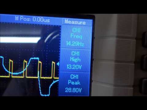
So I made new spacer bushings to open up all four air gaps from 1/4" each to 3/8" each. This made a big difference in both drag force and overall performance. The max voltage from the generator went down some, but it can be fully loaded, shorted out, or charge a battery with only a slight reduction in RPM now and only a slight increase in motor current draw from 1 amp to 1.1 amp max! I hooked both scope channels up, one to the motor and one to the generator. The motor was running 4000 RPM at 1 amp draw and the generator was running 1200 RPM under load. The generator was charging a battery with a 400 ma load hooked to it and maintaining 12.83 volts.The motor flyback recovery circuit was charging another battery with a 500 ma load attached and maintaining 13.58 volts.
It ran this way for a good two hours or so and everything remained steady except for a slow decline in the run battery voltage from 25 volts under load to 24 volts under load. I thought this wasn't too bad for using 5 AH sealed batteries delivering current at the C5 rate. The charge rates for both batteries under charge had to be controlled with loads to keep them from overcharging. And after resting for an hour both charge batteries were setting at 13.1 volts! Makes me wonder what would happen with a battery rotation system in place for this set up?
At .9 amps / 13.2 volts out it was powering an 11.88 watt electrical load while pulling 1 amp at 24.5 volts for 24.5 watts being delivered from the run battery. Plus it was wasting some mechanical energy in the bearings and drive belt. There was little or no heating in any of the electronic devices.Comment
-
-
Hi Brian,
Thanks.Originally posted by Brian McNece View Post Finally got some pictures and a short video.
Since opening up the air gaps helped so much while running at 24 volts, I decided to try it again at 12 volts last night. I used the same loads as when it was running on the higher voltage. 500 ma on the radiant recovery battery and 400 ma on the battery being charged by the flux gate generator.
These loads were a little too much as the batteries both lost voltage while being resupplied, but the motor and generator both ran much faster than with the narrower gap, and didn't slow down much under load. The motor current draw was only 900 ma and changed very little when the generator was under load. The radiant recovery battery produces no drag or run current load at all on the motor. This energy recovery is basically a freebee!
So instead of pulling the generator at 550 RPM under load like before with 12 volts input, it now pulls it at 850 RPM with about the same load applied. According to my calculations, the two charge batteries averaged supplying 11.3 watts together while the motor was being fed with an average of 10.625 watts over the two hour run period. This is still probably under-unity because the charge batteries lost some charge. The load was greater than the recharging current to each battery. But I still found the results pretty interesting. With a better, more efficient motor and faster generator speed, it should do much better!
Comment
-
Hi All,
Did a little more experimenting with this set up today. First I wired the two motor coils in parallel instead of in series. It didn't like that at all!! Pegged the ammeter on start up and drew over 2 amps when it got up to speed. The speed was only slightly faster than when the coils were in series. Plus the FET was over heating! So I shut it down right away and put the coils back in series.
Then I decided to hook the the charge recovery battery up in common ground mode (generator mode or mode 2) and was pleasantly surprised with the results!! The motor was drawing just under 800 ma, pulling the generator at 900 RPM, and keeping the recovery battery fully charged while powering a 600 ma load of LED's. The generator was also keeping the other charge battery charged while powering between 200 and 300 ma of LED's.
This combination now appears to be putting out more than it's consuming! Of course with out battery rotation, the run battery is slowly losing charge and letting the motor slow down. If I remove the loads from the charge batteries they will overcharge.Comment
-
Hey Gary,
Great progress on your end with this project - your experience and knowledge are making it happen. When one considers some of the mumbo jumbo and speculation presented in posts from others on various threads your objective viewpoint and solid data are a great example that others should seek to emulate.
If this Alt E ship is to continue to gain credibility, well it is this kind of positive and objective work that will continue to move it forward.
Thanks for sharing your passion, and nice work Mon,
Yaro Yaro
Yaro
"The Universe is under no obligation to make sense to you." -Neil Degrasse TysonComment
Comment