Announcement

Collapse
No announcement yet.

John Bedini's Magnetic Model

Collapse
X
 
  • Filter
  • Time
  • Show
Clear All
new posts

  • This image will explain it a little more, I doctored up this image of John’s notes to show how to run a motor or generator and the waveform it produces.

    Click image for larger version  Name:	IMG_3955.jpeg Views:	0 Size:	679.7 KB ID:	74508

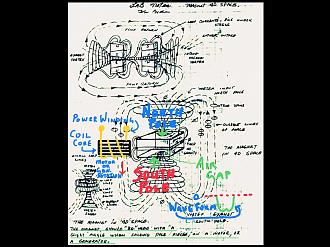
    if you have no air gap in between the magnet and just use one solid magnet instead of two, you will get this waveform John Bedini describes as a Generator waveform, you spin the generator rotor one direction and get a stronger peak in one direction and spin the generator rotor the other direction you get a stronger peak waveform in the other direction. Just as John describes. Watch the short vid.

    https://youtube.com/shorts/wLVLHQhMM...zCsr6NkQ8dbBfM
    Last edited by Dave Wing; 12-03-2023, 12:51 PM.

    Comment


    • Bearden talks of this waveform, where it warps (spins) one way it is positive and warp (spin) it the other way it is negative.

      https://youtube.com/shorts/zxqjdlfJL...POzVWiXM0RKOhl

      Comment


      • Regarding this statement from John’s webpages, Gabriel Kron is quoted… “When the generator current is positive the circuit draws energy from the source, and when the current is negative the circuit pumps back energy into the source. At zero generator current the circuit neither gives nor takes energy, and theoretically the generator may be removed.”

        A North Pole face produces an alternating current type of waveform, it has a positive peak and a negative peak when the coil passes the face of a North Pole. The positive part of the waveform will charge the secondary battery and the negative part of the waveform will charge the primary battery.

        If we use the magnets to produce all negative waveforms it can help us recharge the primary battery or power the motor and it would aid us in energy efficiency and may even allow one to disconnect the primary battery from the machine and have it self power the system. But how do we do this? This is the area I am currently working in.

        Just so it is totally clear “At zero generator current the circuit neither gives nor takes energy, and theoretically the generator may be removed.” The generator in this case is the primary battery and it may be removed if the auxiliary system generator can supply enough current, so the battery doesn’t therefore need to supply current to the system or motor.

        Click image for larger version  Name:	IMG_3961.jpeg Views:	0 Size:	170.2 KB ID:	74528
        Last edited by Dave Wing; 12-20-2023, 12:28 AM.

        Comment


        • Here is a schematic of the Ron Cole generator…

          Notice it uses bar magnets with the poles outwards, as labeled in the schematic. Go up and look closer of the images of this machine you can see that there are 3 rectangular bar magnets stacked one on top of the other to make one bar magnet. North on one end and South on the other end.

          This particular machine makes a positive then a negative waveform when rotated in one direction and if rotated in the opposite direction it will be a negative then a positive waveform. When looking at the peaks of both the positive and negative waveform’s you see a dip in the peak of the waveform, this dip is from the air space between each rotor magnet.

          The image below was taken from John Bedini’s pages, here is the link… https://www.icestuff.com/~energy21/bedmot.htm

          Click image for larger version  Name:	IMG_3958.jpeg Views:	0 Size:	806.5 KB ID:	74522
          Last edited by Dave Wing; 12-04-2023, 06:29 AM. Reason: Corrections and adding more info

          Comment


          • The SSG splits the positive and negative waveform of the North Pole into two separate charging signals that each charge the primary and secondary batteries separately. The secondary battery receives a extra additional portion which is the coil collapse.

            Click image for larger version  Name:	IMG_3964.jpeg Views:	0 Size:	694.5 KB ID:	74557


            This diagram below is exactly what is happening with a cycle of the SSG when using a power coil and a North Pole rotor, anything over 6 volts will charge the batteries in the image below.

            Click image for larger version  Name:	IMG_3966.jpeg Views:	0 Size:	531.4 KB ID:	74556
            Last edited by Dave Wing; 12-04-2023, 03:34 PM.

            Comment


            • I hope it is clear that a North Pole generates a positive and a negative waveform, the SSG handbooks also show this aspect. When you install magnets on their sides into any SSG rotor and hook a scope across the power coil and display the waveform you will find the waveform will become more positive when you rotate it in one direction and more negative when rotated in the other direction. On my machine this equates to 2:1 charging ratio (ratio being: 2 = primary charging to 1= secondary charging) or the reverse if you rotate it the rotor in the other direction (ratio being: 1 = primary charging to 2 = secondary charging).

              This is would be an asymmetrical waveform producing machine which I believe makes a motor or generator very efficient.


              Again in this video John talks about the generator waveform that may look like a more positive or may look like a more negative waveform.

              https://youtube.com/shorts/wLVLHQhMM...F329egYA2nYQ-7


              Click image for larger version  Name:	IMG_3404.jpeg Views:	0 Size:	186.5 KB ID:	74564
              The image above is the screen shot image of John’s generator waveform drawings I hand drew in the other portion of the waveform so it could be understood better.

              The image below is my test wheel scope shot, the wheel consists of 3 magnets on the wheel, with two North poles facing the power coil and the middle magnet is laid upon its side and produces the waveform John Bedini shows and Thomas Bearden talks about. If you rotate the wheel one way the center waveform stays with the bulk of the waveform being negative and if the wheel is rotated the other way the bulk of the waveform is more positive. This was just a test so I could compare the waveforms on the scope.

              Click image for larger version  Name:	IMG_3633.jpeg Views:	7 Size:	191.1 KB ID:	74565
              Last edited by Dave Wing; 12-07-2023, 04:25 PM.

              Comment


              • Here is some more info… The highlighted words, in the image were taken from this thread.

                https://www.energyscienceforum.com/f...age4#post29873

                Click image for larger version  Name:	IMG_3992.jpeg Views:	0 Size:	235.1 KB ID:	74572

                Click image for larger version  Name:	IMG_3994.jpeg Views:	0 Size:	532.1 KB ID:	74575

                If you build the rotor and coil sections with increased length, as described in the above image, you can even turn a conventional generator and have it send a high rate of feedback to the front end. Smaller motor rotor diameter will give more motor speed to turn a generator, you will sacrifice some tourque to get the proper speed, to get enough output from your generator. That is why we elongate the rotor and coils to overcome our tourque losses associated with increased motor speeds.

                As Paul Babcock explained longer larger diameter wire will increase flyback energy and give you a lot more magnetism in your coil core, for the same amount of energy expended. If you take two coils and compare them, one with 40 awg wire at 5 ohms and then another 10awg wire coil at 5 ohms which one has more magnetism and which one will yield more flyback energy? The 10 awg coil could be 30 times the size of the 40 awg coil. One could easily see a coil 30 times bigger will produce a lot more rotor torque and flyback energy than the smaller coil. It should also be again noted that each coil (10 awg vs 40 awg) will have the same current draw, from the primary battery, as ohm’s law states. So let’s make those coils big and quit messing around with those flea power machines with small dinky coils.

                Dave Wing
                Last edited by Dave Wing; 12-12-2023, 09:21 AM.

                Comment


                • Referring to post 351, those waveforms are what are termed as monopoles. If you look at these images you will see these configurations make the monopole waveform.

                  Click image for larger version  Name:	IMG_4019.jpeg Views:	0 Size:	459.6 KB ID:	74585

                  The above image is from Thomas Beardens writings on how the bedini machine works, the waveform produced is as found in post 354.


                  Click image for larger version  Name:	IMG_4081.png Views:	0 Size:	23.7 KB ID:	74586 Click image for larger version  Name:	IMG_4080.png Views:	0 Size:	35.7 KB ID:	74588
                  Click image for larger version  Name:	IMG_4090.jpeg Views:	39 Size:	429.7 KB ID:	74594


                  These two images are screen shots from the presentation found here: https://emediapress.com/shop/free-energy-generator/


                  John Bedini’s monopole enegizer was designed to use the North/ South rotor magnets together while interacting with an iron core power coil, in the manner shown, or you can place a single magnet on its side. The zero force motor also produces this waveform only if you were to use an all south or all north rotor with no alternating nsns magnets. If you use north and south poles in your zero force motor it produces a positive and negative AC waveform.

                  Dave Wing
                  Last edited by Dave Wing; 12-21-2023, 05:16 PM.

                  Comment


                  • All the above configuration’s do produce this monopole waveform, here the generated voltage peak is negative, spin the rotor the other direction the voltage peak is positive.

                    Click image for larger version  Name:	IMG_4083.jpeg Views:	0 Size:	199.2 KB ID:	74592


                    Dave Wing
                    Last edited by Dave Wing; 12-17-2023, 07:28 PM.

                    Comment


                    • Here is a short on what John dislikes about conventional motors and generators that use the North and South configurations. He says…
                      “change the situation into monopoles”.

                      https://youtu.be/IkkOEbgZo-c?si=lgMopgj_SGQskVee
                      Last edited by Dave Wing; 12-18-2023, 04:54 AM.

                      Comment


                      • Dave,

                        An awesome compendium of related and specific Bedini-Cole information that is much more insightful than the general fodder. You are a good man to share all this valuable information along with your insights. Curious as to where you found the elusive Ron Cole files?

                        Anyway, I am still in a sabbatical mode, but that may change in the near future thanks to your insights on this thread.

                        Happy Holidays Brother,
                        Yaro
                        Yaro

                        "The Universe is under no obligation to make sense to you." -Neil Degrasse Tyson

                        Comment


                        • Good to hear from you Yaro, sounds like you are doing well!

                          I found the files on ConCen, torrent sharing site, the Ron Cole stuff is there located in the Cejka files. There are some of the Energy From The Vacuum vids as well. There is one file on John Bedini called “Free Energy Corrected” it is a corrupt file. Just do a search on Bedini.

                          You cannot purchase this information anymore so I think it is fine to share the files.

                          Dave Wing

                          Comment


                          • You will notice in this Nexus magazine article the diagrams have a dc motor turning an “Energizer” or G-Field generator. John has always said the SSG was not an electric motor but an energizer.

                            The SSG energizer can have a capacitor installed in-place of the primary battery and it will charge the secondary battery in that condition. Remember I posted in post #350 that the SSG sends a charge to both primary and secondary batteries while rotating, if the magnetics and coils will produce enough amplitude to do so.

                            As a side note… I would like this to be clear, the motor in drawing from post #352 is a pulse driven DC motor that produces a minimal positive waveform (positive CEMF) at high rpm. It does not charge the secondary battery very well, because of this, also the consumption current of the machine is very low as a result. (See: Peter Lindemann’s video Electric Motor Secrets series of videos).

                            The step down transformer aids in the reduction of CEMF drag and amperage increases, associated with high rotor rotational speed. The coil collapse, flyback, still makes its way through the transformer with no issues, to the primary battery as configured in drawing on post #352. The high tourque low current draw motor, in post 352, is designed to turn an Energizer, G-Field, or conventional dc generator as spoken of by John Bedini.

                            John Bedini said he combined the motor and energizer into one unit and it became the SSG. I am simply reconverting it back to a separates again, with a permanent magnet reluctance pulse Motor and an Energizer so it can be studied in raw form.

                            So far I have made a pulse motor with good torque, a single motor coil is 10 pounds consisting of 3 strands of 20 awg wire wound in parallel, the three strands in parallel are 3 ohm coils with 2” wide by 3/4” thick and 5” long core, the rotor magnet is 2” x 1” x1” Neo magnets placed upon their sides, as seen in my YouTube videos. I plan to improve the motor by making even larger coils, perhaps with 10” x 3/4” x 5” cores filled with 12 or 10 awg wire and the rotor length, magnets included will be increased to 10” long x 1” x 1” on a 3” diameter rotor. These coils will be big but will produce more flyback energy, stronger magnetic field to interact with my longer rotor. I will do this as time and money permits.

                            As it stands right now the my permanent magnet pulse motor under load draws 170 milliamps under full load at 3000 rpm on an applied voltage of 48 volts. Which is just over 8 watts consumed at full load. No load it will run over 8000 rpm at 48 volts. Paul Babcock’s videos have been a great in helping me out, they are called Magnetic Energy Secrets. Found on Aaron’s site.

                            Has anyone built a zero force motor and made the coils and rotor elongated, say from 2” to 12” plus? What were the results? Did you try longer and larger diameter magnet wire? I would love to hear of your results.

                            In my opinion one of the biggest draw backs in any electric motor today is 1) Lack of fill (room to add larger diameter wire, with far greater lengths and much more turns). 2) Electric motors are not built with long enough stators and coils to match. To me this is the real secret of free energy, Joe Newman used large heavy, long rotors and coils. If you do the same you will see improvement in your builds. We should be thinking about converting existing electric motors.


                            Dave wing

                            Click image for larger version  Name:	IMG_4091.jpeg Views:	0 Size:	657.3 KB ID:	74599 Click image for larger version  Name:	IMG_4092.jpeg Views:	0 Size:	722.8 KB ID:	74600 Click image for larger version  Name:	IMG_4093.jpeg Views:	0 Size:	760.9 KB ID:	74601
                            Last edited by Dave Wing; 01-06-2024, 10:21 AM.

                            Comment


                            • Here is a short video on how to create the waveforms of Ron Cole, John Bedini and Thomas Bearden have shown and talked about.

                              https://youtu.be/5mbhBMLY91c?si=hC4fe0lKwRjl2du6


                              Below is the configuration used in the video link.
                              Click image for larger version  Name:	IMG_3966.jpeg Views:	0 Size:	531.4 KB ID:	74603


                              Dave Wing
                              Last edited by Dave Wing; 12-21-2023, 05:56 PM.

                              Comment


                              • Here is John Bedini speaking of a G-field generator and building zero’s.

                                https://youtu.be/tsnJXP0jKdo?si=joUc6q1COxWpovDn
                                Last edited by Dave Wing; 12-21-2023, 05:20 PM.

                                Comment

                                Working...
                                X