Announcement

Collapse
No announcement yet.

Zero Force Motor Replication Project

Collapse
X
 
  • Filter
  • Time
  • Show
Clear All
new posts

  • ZFM Proto Iron Rotor and Vid 4

    New Year's greetings to all,

    The ZFM Proto project has been progressing with the initial testing of the Iron rotor over the past week or so. Sad to say the initial results of the Iron rotor's performance were inferior, to a certain degree, over the Aluminum rotor design. However, with judicious and careful tweaking the speed (RPM) was considerably improved. The self aligning pillow block bearings are difficult to align perfectly - this bearing method requires review and/or modification. Below is the image of the Iron rotor with the Neo's glued in place - note Loctite AA 332 adhesive was used for the installation of the Neo's. Should be good to about 15,00 RPM if properly applied and installed.

    Click image for larger version

Name:	IMG_20161225_065155_913.jpg
Views:	1
Size:	473.7 KB
ID:	49125

    The test data for the Iron rotor is as follows for 65 to 70 degree firing arc duration:
    12v - 1485 RPM @ 0.84 A
    24v - 2990 RPM @ 1.23 A
    36v - 4370 RPM @ 1.42 A
    The motor will slowly accelerate by steps to the following:
    36v - 4400 RPM @ 1.40 A
    36v - 4595 RPM @ 1.33 A
    36v - 4900 RPM @ 1.32 A

    The above does indicate that there are certain peculiarities to its operation. The ZFM is very sensitive to the voltage input value.

    If the firing arc duration is decreased to the recommended value of 45 - 50 degrees then the following are observed:
    12v - 1150 RPM @ 0.63 A
    24v - 2100 RPM @ 1.09 A
    36v - 2990 RPM @ 1.18 A

    The torque is low for this configuration also!

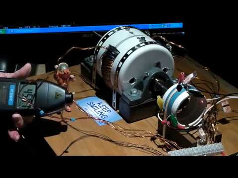
    So here is the video of the Iron rotor in operation - please note that the initial RPM value of 3500 for 36 volt operation is incorrect and should be 4500 RPM - tongue tied...


    This is about enough for this phase - more to come.

    Happy New Year,
    Yaro
    Yaro

    "The Universe is under no obligation to make sense to you." -Neil Degrasse Tyson

    Comment


    • ZFM Proto Performance Update

      Hello All,

      Over the course of this month sporadic testing has been accomplished on the ZFM Proto and while there is no video this time (thought that the readership had enough of the squiggly lines) there are interesting points from the latest testing from Jan 9 and later.

      The following data is using the maximum firing arc of about 70-75 degrees:

      12v 1800 RPM @1.0A
      12v 1921 RPM @1.0A
      12v 2370 RPM @0.9A
      The RPM slowly increases over a few minutes.

      24v 4026 RPM @1.30A
      24v 4045 RPM @1.31A
      24V 4470 RPM @1.30A
      Same increase in RPM over time.

      36V 5425 RPM @1.57A
      36v 5762 RPM @ 1.58A
      36v 5910 RPM @ 1.50A

      Advancing the timing a bit yielded the following for 36v:
      36v 6070 RPM @1.48A
      36v 6123 RPM @1.44A
      36v 6378 RPM @1.43A

      The motor at this point is rotating at a decent speed and the starting torque appears to be improving. The following test from Jan 18 starts getting into a different zone of performance as the timing is further advanced and the motor begins to display some unusual characteristics that may be related to frequency and harmonics.

      36v 7300 RPM @1.45A
      36v 7400 RPM @1.33A
      36v 7900 RPM @?

      Once the motor hit an RPM of ~7000 it accelerated up to 7900 RPM. The motor sounded differently from the previous tests and the torque was improved - in this instance, unfortunately, a video was not taken. Too many things to control and not enough hands available. You should note that the amperage draw from the battery is remaining relatively stable or diminishing as the RPM increases. The coils were relatively cool, but the resistors on the circuit board were hot.

      It appeared that the firing point for the coils was advanced well into the coil area. The timing arrangement was closely examined after the test was completed and this indeed appeared to be the case. The following day I was not able to duplicate the above performance - everything was untouched and the same. Certainly a point of interest and bafflement by the awakening of the "Beast".

      The setup has been sitting for a week now and I will try to duplicate the above behavior if possible. This is one strange motor!

      More to come,
      Yaro
      Yaro

      "The Universe is under no obligation to make sense to you." -Neil Degrasse Tyson

      Comment


      • ZFM Proto Video 5 with Aluminum Rotor

        Hello All,

        I spent the last few days modifying the existing ZFM Proto to correct and improve most of the nagging details that limited performance. Most of the critical steel fasteners were replaced with 18-8 Stainless Steel bolts. Additional tweaks were made to the bearing alignment and reed switch position. The biggest impact came from replacing a small steel bolt directly under the timing rotor which was influencing the timing and firing arc duration at high RPM - big change!

        The Iron core motor rotor was removed and replaced with the original Aluminum rotor - virtually identical dimensions and Neo's. This was done to establish additional baseline information for comparative purposes to the Iron core rotor.

        The last tests in the previous post noted some unusual behavior in the timing arc and firing positions - these were subsequently attributed to the small steel bolt under the Timing Rotor and two SSG wheel magnets that were a bit too close to the Timing Rotor. Amazing how the SSG magnets influenced the the timing from 6" to 8" away.

        This unusual behavior was deemed well worth the effort to document and to create a short show and tell video to note the influence of a concentrated magnetic field. For this video the timing arc was set for a 45 to 50 degree firing duration and 36 volt operation - essentially trying to limit the maximum speed.

        The influence of the C8 magnet pair on the coils was dependent on the polarity facing the coils:
        The south facing pole surface would add some additional speed (~250 RPM) to the motor.
        The north facing pole surface would lower the speed about the same amount.
        Distance from coils ~1".

        The influence of the C8 magnet pair was much more pronounced when facing the timing rotor outboard face, one could hear the speed increase from up to 10" away or more. The Timing Rotor Neo's had their south face away from the motor and the SSG magnets had their north face towards the timing wheel for the speed increase; with the SSG magnets' south facing the ZFM could be nearly stalled. Check out the below video.


        Here is the operational data:
        24v 3028 RPM 0.82A without magnets
        24v 4936 RPM 1.20A with North facing magnets

        36v 4590 RPM 0.93A without magnets
        36v 6500+RPM 1.40A with North facing magnets

        A simplistic explanation could be that the SSG magnets' position enhances the strength of the overall magnetic field that triggers the coil firing and expands the firing arc duration. It has been observed in prior tests that expanding the firing arc duration increases the motor speed along with the battery amp draw. The applied voltage is also a factor...

        Still remains one strange motor...

        All very interesting and, as usual, more to come,
        Yaro
        Yaro

        "The Universe is under no obligation to make sense to you." -Neil Degrasse Tyson

        Comment


        • Yaro,
          thanks for letting us know what the negative influences were in a working example. That is as valuable to me as what works.

          Comment


          • Originally posted by Michael Luton View Post
            Yaro,
            thanks for letting us know what the negative influences were in a working example. That is as valuable to me as what works.
            Michael - thanks for the spot on comment! Success with any experimental device always depends on the yin-yang interplay of the results. Any astute and successful experimenter uses the failures and disappointments to advance the experiment to higher level of understanding.

            Yaro
            Yaro

            "The Universe is under no obligation to make sense to you." -Neil Degrasse Tyson

            Comment


            • Very well said !!!

              Comment


              • Originally posted by Yaro1776 View Post
                Hello All,

                I spent the last few days modifying the existing ZFM Proto to correct and improve most of the nagging details that limited performance. Most of the critical steel fasteners were replaced with 18-8 Stainless Steel bolts. Additional tweaks were made to the bearing alignment and reed switch position. The biggest impact came from replacing a small steel bolt directly under the timing rotor which was influencing the timing and firing arc duration at high RPM - big change!

                The Iron core motor rotor was removed and replaced with the original Aluminum rotor - virtually identical dimensions and Neo's. This was done to establish additional baseline information for comparative purposes to the Iron core rotor.

                The last tests in the previous post noted some unusual behavior in the timing arc and firing positions - these were subsequently attributed to the small steel bolt under the Timing Rotor and two SSG wheel magnets that were a bit too close to the Timing Rotor. Amazing how the SSG magnets influenced the the timing from 6" to 8" away.

                This unusual behavior was deemed well worth the effort to document and to create a short show and tell video to note the influence of a concentrated magnetic field. For this video the timing arc was set for a 45 to 50 degree firing duration and 36 volt operation - essentially trying to limit the maximum speed.

                The influence of the C8 magnet pair on the coils was dependent on the polarity facing the coils:
                The south facing pole surface would add some additional speed (~250 RPM) to the motor.
                The north facing pole surface would lower the speed about the same amount.
                Distance from coils ~1".

                The influence of the C8 magnet pair was much more pronounced when facing the timing rotor outboard face, one could hear the speed increase from up to 10" away or more. The Timing Rotor Neo's had their south face away from the motor and the SSG magnets had their north face towards the timing wheel for the speed increase; with the SSG magnets' south facing the ZFM could be nearly stalled. Check out the below video.


                Here is the operational data:
                24v 3028 RPM 0.82A without magnets
                24v 4936 RPM 1.20A with North facing magnets

                36v 4590 RPM 0.93A without magnets
                36v 6500+RPM 1.40A with North facing magnets

                A simplistic explanation could be that the SSG magnets' position enhances the strength of the overall magnetic field that triggers the coil firing and expands the firing arc duration. It has been observed in prior tests that expanding the firing arc duration increases the motor speed along with the battery amp draw. The applied voltage is also a factor...

                Still remains one strange motor...

                All very interesting and, as usual, more to come,
                Yaro
                Hi Yaro,

                Interesting effect, however i think it is the negating/ additive influence of the SSG magnet on the Hall pick up, that is decreasing and increasing the RPM respectivily in each case..
                Rgds,
                Faraday88.
                'Wisdom comes from living out of the knowledge.'

                Comment


                • Originally posted by Yaro1776 View Post
                  Michael - thanks for the spot on comment! Success with any experimental device always depends on the yin-yang interplay of the results. Any astute and successful experimenter uses the failures and disappointments to advance the experiment to higher level of understanding.

                  Yaro
                  My Full mark to you Yaro!!!!
                  Micheal Faraday whom I follow so much quoted '' Try desperately to succeed and do not hope for success''
                  Rgds,
                  Faraday88.
                  'Wisdom comes from living out of the knowledge.'

                  Comment


                  • I have always wanted to ask this questions so here it goes:

                    Does the ZERO FORCE MOTOR coil configuration have more torque than the regular SSG coil configuration??

                    Same coil with same ON TIME, etc, would give more torque to the rotor if the coil is placed like in the ZERO FORCE MOTOR instead of facing the magnets like the SSG ??.

                    I remember some John's Lab Notes where there are some notes about that, I think it said that regular SSG coil would be 23% efficiency and ZERO FORCE MOTOR coil would be like 90% efficiency.

                    I have tried to find those lab notes but I can't find them, and I don't remember where I saw them.

                    best.

                    Alvaro

                    Comment


                    • Alvaro,

                      Yes a ton more torque not even a fair race. the SG charges batteries the ZFM is a torque motor like the Window motor

                      Tom c


                      experimental Kits, chargers and solar trackers

                      Comment


                      • Originally posted by Tom C View Post
                        Alvaro,

                        Yes a ton more torque not even a fair race. the SG charges batteries the ZFM is a torque motor like the Window motor

                        Tom c
                        I see, so the zero force motor does not generate radiant spike? the ON time on the ZFM is too long ? that why more torque and less charging?

                        Comment


                        • I did not say it does not charge because it does, its a different operation, the ZFM circuit (full bipolar switch) is designed to drive a motor. For the SG the wheel is just a trigger to generate the flip on the core to open the base. its a mechanical magnetic switch. that is why we look for the lowest friction co efficient in the bike wheel, we don't want to exert any more energy than we need to turn the bike wheel.

                          Tom C


                          experimental Kits, chargers and solar trackers

                          Comment


                          • Originally posted by AlvaroHN View Post
                            I have always wanted to ask this questions so here it goes:

                            Does the ZERO FORCE MOTOR coil configuration have more torque than the regular SSG coil configuration??

                            Same coil with same ON TIME, etc, would give more torque to the rotor if the coil is placed like in the ZERO FORCE MOTOR instead of facing the magnets like the SSG ??.

                            I remember some John's Lab Notes where there are some notes about that, I think it said that regular SSG coil would be 23% efficiency and ZERO FORCE MOTOR coil would be like 90% efficiency.

                            I have tried to find those lab notes but I can't find them, and I don't remember where I saw them.

                            best.

                            Alvaro
                            Here Alvaro...


                            Check out out this video and or channel for a good comparison between the two types of systems, the zero force motor and SSG solenoid versions... Notice the acceleration differences. Anyway http://youtu.be/Dj-fOh1Wz_Q

                            People should really also pay attention to multi strand coils and the energy savings and magnetism gains of multi filar coils... It is one thing John Bedini said that was left out of his patents by the patent office. Notice that for an extra 10 milliamperes you will get 75 percent more magnetic force acting upon the magnetics of your rotor. Which equates to more speed and or a more powerful machine for little extra energy input. Ron's notes above say multi filar coils defy "FUNDEMENTAL OHMS LAW" and look at point number 4. " NEW INVERSE SQUARE LAW RATIO EFFECT"

                            Now if it were me I would use very small gauge wire like 26AWG - 45AWG wire in my multi stranded coils (multi filar coils) and experiment in this area with different lengths too.

                            Dave Wing
                            Attached Files
                            Last edited by Dave Wing; 02-04-2017, 07:01 PM. Reason: Changes, Additions

                            Comment


                            • Hi Tom and Dave. Dave those where the lab notes I was talking about tnx! Now I am in a hurry but I will look at the vid later.

                              Tom, what would happen if the BIPOLAR SWITCH is set to have a very small ON time, like the SSG circuit, would it charge as good as the SSG? and still have more torque?

                              Comment


                              • Originally posted by AlvaroHN View Post
                                Hi Tom and Dave. Dave those where the lab notes I was talking about tnx! Now I am in a hurry but I will look at the vid later.

                                Tom, what would happen if the BIPOLAR SWITCH is set to have a very small ON time, like the SSG circuit, would it charge as good as the SSG? and still have more torque?
                                you can use the bipolar switch on your SSG setup. One of the main diff between the switches, the SSG switches the Neg terminal of the battery to the coil - the bipolar switches both +and-. you have to tune to get them to do it simultaniusly - that's the trick and you have to get them to switch off simultaneously to get good charging. This is one reason you need a matched set. physics isn't going to let you go, in order to get the power, you need longer on time. What we do with that on time is up to us.

                                Comment

                                Working...
                                X