 Tweet
Tweet
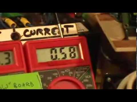
A multimeter is actually not that far off - the proof would always be to measure the output of a primary using 3amps (or whatever) to the SSG over a period of time, calculate the joules out and use the graph to monitor your drain.
Charge it back up, then do the same thing using a resistive load of the same value...
TinselKoala shows a down and dirty quick way to see how far off your multimeter is in averaging the spike draw from the primary:
Charge it back up, then do the same thing using a resistive load of the same value...
TinselKoala shows a down and dirty quick way to see how far off your multimeter is in averaging the spike draw from the primary:

 It's a pain matching up 8 transistors again


 This is almost exactly how John Bedini's 10 coil scope behaves. Nice Work BTW that's a clean build you have there! I would love it if you did a few runs just like this before making everything line up perfectly. Then see if there is any difference...
Comment