Announcement

Collapse
No announcement yet.

Down The Rabbit Hole!

Collapse
X
 
  • Filter
  • Time
  • Show
Clear All
new posts

  • Down The Rabbit Hole!

    I built my first SSG Monopole. I'm very excited that it works! (Though not perfectly, so I'll need some help troubleshooting.)


    Here's a video followed by a description of what you're looking at.


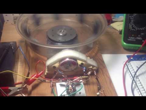
    The circuit is shown in the video. I built this after reading the SSG Beginner Guide.

    Parts details:
    - The power supply is a 12V 1amp trickle charger.
    - The transistor is a 2N3055
    - The coil is bifilar - 100ft of #24 and #20.
    - The neon buib is 110V from Radio Shack. (I don't know if it's Ne-2)
    - Grain-of-wheat lamp is the smallest at Radio Shack.
    - The core is filled with 1/8" plain welding rod from Home Depot. Seems to work fine.
    - Diodes are standard 1N4001 and 1N4007.
    - The rotor is made from a random plastic plate cover thing with a hole in it from a thrift store.
    - The spindle/bearings are from a hard drive - it happened to fit right inside the plate cover, though it's wobbly.
    - Magnets are standard 1-7/8" x 7/8" x 3/4" mounted inside the rotor -- no flying magnets to worry about.
    - Coil to magnet separation is about 1/4"
    - Resistance on this run was about 400ohms.
    - RPM is about 330 in this video. I've gotten it up to 440 RPM.
    - I believe it's running in attraction mode here. I paid no attention to N vs. S polarity, simply switching the circuit polarity until it worked.


    It runs well and charges the 3ah battery at a decent rate, but it has problems:


    -- Biggest problem: The neon always stays on.
    -- The grain-of-wheat lamp doesn't light up, unless I drop the base resistance all the way down.)


    It'd be great if someone could help troubleshoot it. Here are some things I've noticed.

    - The neon lamp brightens correctly when I disconnect the charging wires.
    - The neon is always on. (ie. flashing very fast)
    - When I drop the base resistance, the neon becomes less continuously lit, ie. it flickers more.
    - The voltage measured at the power supply is 16-17V. (Not the 12.8V the power supply puts out.)

    This system is no longer functional. After getting about a day's use out of it, a small wire adjustment triggered a meltdown. First the neon turned off. The transistor overheated (and gave me a good blister). Then the output diode literally melted.

    Given that the neon responds to the charging circuit, my first thought is that I may have had a leaky output diode. (It measured the correct resistance, as far as I knew, but I wouldn't have caught a leak). Maybe this could explain the high input voltage. (Or is it supposed to be that way? - I don't know.)

    I need to get more parts before I can continue, but I'm not sure I can afford it right now. Maybe someone can advise before I do so.


    In any case, I'm excited! Down the rabbit hole!


    Rik
    Last edited by mobilerik; 10-01-2013, 10:25 AM.

  • #2
    You have built a very non standard system so it is hard to say what could be the problem but I will try. .

    First for your transistor get an MJL21194 instead. I have used both and those 3055's are very tricky to work with. They have a much lower tolerance for throughput current.

    For the record your grain of wheat is not supposed to light up. That does not mean it is not doing anything in the circuit.

    The first use of them in an oscillator was back in 1939 by Bill Hewlett. I have run circuits with and without them, it will work either way but you should experiment to find out the effect.

    Have a look at this for a better understanding:


    For the neon lighting up all the time, what is the condition of your charge battery? If it has sulphate build up pretty badly than it is not accepting the charge and that is bleeding off into the neon. Charge it and discharge it a little at a time to get it to start accepting the charge. You may want to add more resistance to your base to help with this as well. Again it is hard to say just from a video.

    I'm sure you can get your machine to work but you will have to develop an understanding of how it works. That is why people are encouraged to build the standard model, it is proven to have the correct values and it makes it easy to troubleshoot when we know what you are working with

    I wish you good luck---Bob

    Comment


    • #3
      Hi Bob. Thanks for your comment. I forgot to mention: The machine works! Just not perfectly. The battery is good, and it discharges and charges up fine both on a standard charger and on the energizer. The neon stays lit whether the battery is charging up from 12.5v or 13+. Increasing the base resistance doesn't affect the neon.

      I wasn't particularly concerned about the lamp, but it's nice to know it doesn't need to be lit.

      I'll note again that I built this using instructions from the Beginner's Manual. I don't believe it's so 'non standard'. The only diversion from those plans I can see is adding the grain of wheat lamp and pot for adjustment and using an unidentified 110v neon from Radio Shack until I find an Ne-2. Eventually I'd like to try it with the exact parts specified, but I'm nonetheless pleased that it seems to work well using what I could find, albeit with a constant "error message". I'm just curious if someone with knowledge of the circuit can suggest what's likely generating the error message before I swap out parts. Thanks again for your thoughts.

      Comment


      • #4
        I suspect one or more of your magnets could be in an opposite direction of the others. Double check that each one is facing either north or south but consistent with each other.

        If you want it to run it's best you should ensure they are all north towards the coil and the coil is producing a south field.

        Comment


        • #5
          Thanks again Bob. Interesting idea - Why do you suspect one of the magnets may be flipped? How do you think that might affect the circuit to cause the neon to light up?

          I've had that problem before, and it made the rotor wobble, but I don't recall any effect on the neon.

          Update: I just checked. (And often check.) The magnets are all aligned correctly. I'll also note that the video shows magnets double stacked. I've played with it both with and without the extra magnet, and both versions work similarly.

          I'll also note since I haven't that the soldered connections are solid, with negligible resistance. I made sure in the second round, since that was a frequent problem in the first go-around. I also had a problem with a bad pot. However in each case, oddly enough, the behavior of the neon hasn't changed. The only thing that dimmed the neon was dropping the base resistance below 150ohms.

          Here's a direct question - What is the voltage across the power supply supposed to read, assuming it's a 12.8V power supply? Is it supposed to be way higher as mine is, i.e. 16-17V?

          Comment


          • #6
            Well you really should not be using a power supply. I understand you are working with what you have so I'm not going to knock you for it but the system is designed for batteries on the input. That PS may be injecting a little AC which could be causing you some problems. If you have a 12 volt battery around you should try that on the input to see if it clears things up.

            Comment


            • #7
              "Really should not be..." seems a bit strong, since many guides I've read say that it's perfectly fine to use a power supply. BUT I've also seen it specified to use one rated at least 3A. That struck me as odd, since it shouldn't be drawing 3A, but it may be that the 1A supply is undersized enough to be putting distortion into the circuit, which can easily explain misbehaving (and melting) components. In fact my audio experience tells me that trying to push high voltage transients with a normal (undersized) PS will definitely fry your circuit sooner or later. I'll substitute a battery on the next round.

              Overall... good call Bob!

              Comment


              • #8
                Originally posted by mobilerik View Post
                "Really should not be..." seems a bit strong, since many guides I've read say that it's perfectly fine to use a power supply. BUT I've also seen it specified to use one rated at least 3A. That struck me as odd, since it shouldn't be drawing 3A, but it may be that the 1A supply is undersized enough to be putting distortion into the circuit, which can easily explain misbehaving (and melting) components. In fact my audio experience tells me that trying to push high voltage transients with a normal (undersized) PS will definitely fry your circuit sooner or later. I'll substitute a battery on the next round.

                Overall... good call Bob!
                Just because others have run their SGs on a power supply, doesn't mean it's a good idea. Have you EVER seen John Bedini recommend using a power supply? NO. John has stated many times there is more going on with the currents in the SG than people realize. He is very correct!

                Just because your SG runs at 1A on an analog meter doesn't mean it's drawing 1A continuously. How could this be? Why would running from a battery by different?

                Erik

                Comment


                • #9
                  Hi Erik. Thanks for your reply, although it does seem unduly harsh. I have read many guides, most of which contain quotes from JB, and I believe I actually picked up the power supply recommendation from one of his guides. Of course, I could be mistaken, as with so many sources, it's sometimes tough to keep track of who is making what recommendation.

                  In any case, I don't mind trying things "the wrong way" and making "mistakes," because I find I learn quite a lot that way. Frying components is part of electronics, and experimentation is the heart of science. As I understand it, there's a lifetime of education available in the SSG for those who are patient enough to continue experimenting with it. My goal is to understand the intricacies of this deceptively simple circuit and not get blinded by some unnecessarily hurried "quest for more power".

                  Thanks for your reply though!

                  Comment


                  • #10
                    Mobilerik,

                    We have tried to help you and given you the correct information but you seem to not want to hear it.

                    To give you an idea about your power issues, that bi-filer you are running should only require between 200 - 300ma of current @ 12.7v DC

                    I am a nobody in this arena so you can dismiss me all you want but Erik is one of the few engineers in the world who Mr. Bedini has officially authorized to use his technology.

                    Comment


                    • #11
                      Hey again Bob!

                      I really appreciate your replies and your attempt to help. I apologize if you found my reply to you somehow dismissive... I definitely didn't mean it to sound that way -- I was simply sharing my thought process. Your last post was actually really helpful -- I agree with you that the problem is probably the power supply, and that's what I should have said more clearly. I look forward to checking with a battery next time, and I'll let you know how it goes.

                      My apologies again for any confusion.

                      To give you an idea about your power issues, that bi-filer you are running should only require between 200 - 300ma of current @ 12.7v DC
                      Thanks, that's good info that I couldn't find anywhere, and that's approximately what I measured. The next round I was planning to do a more detailed test of the current consumption. It'll probably be another week or two before I can have the next system ready.

                      Thanks again!

                      Comment

                      Working...
                      X