Announcement

Collapse
No announcement yet.

New Medium Sized Machine

Collapse
X
 
  • Filter
  • Time
  • Show
Clear All
new posts

  • New Medium Sized Machine

    Hello everyone,

    I have been working on a new project and I thought I would kick off a new thread for it.

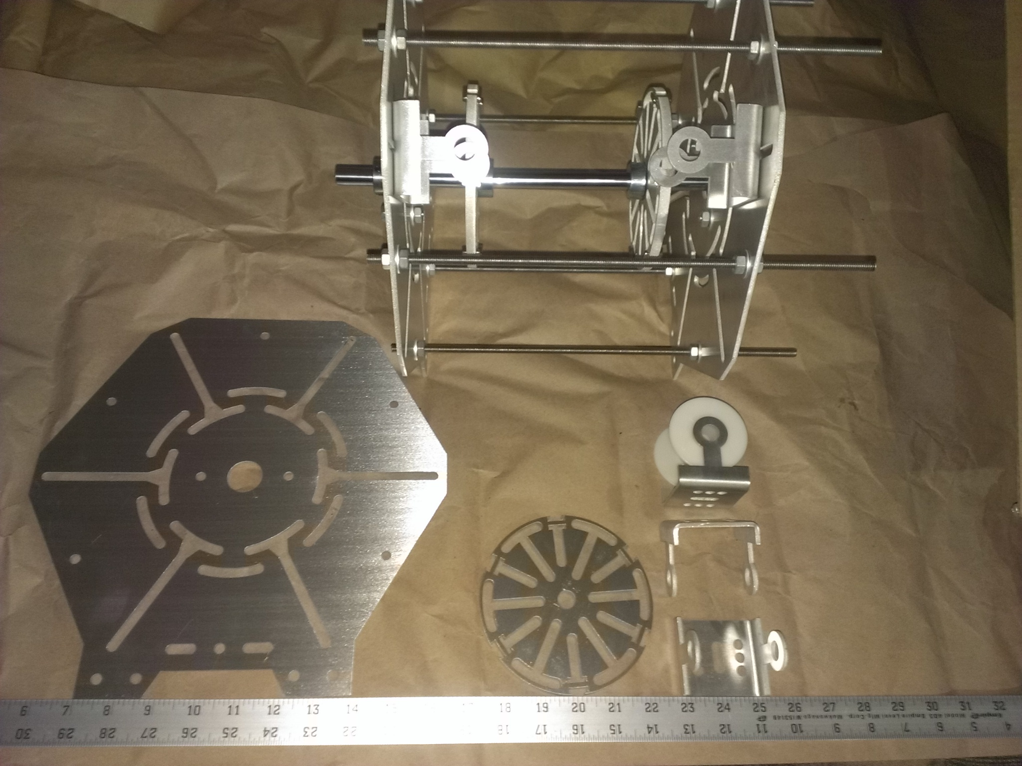
    This machine has a frame of just under 12 inches with 5 inch wheels. When it is fully populated I have room for 12 coils, 6 in the front and 6 in the back using two wheels. The screws and nuts, threaded rods frame and wheels are all aluminum which did drive up the cost a bit but I expect this thing to last for a very long time.

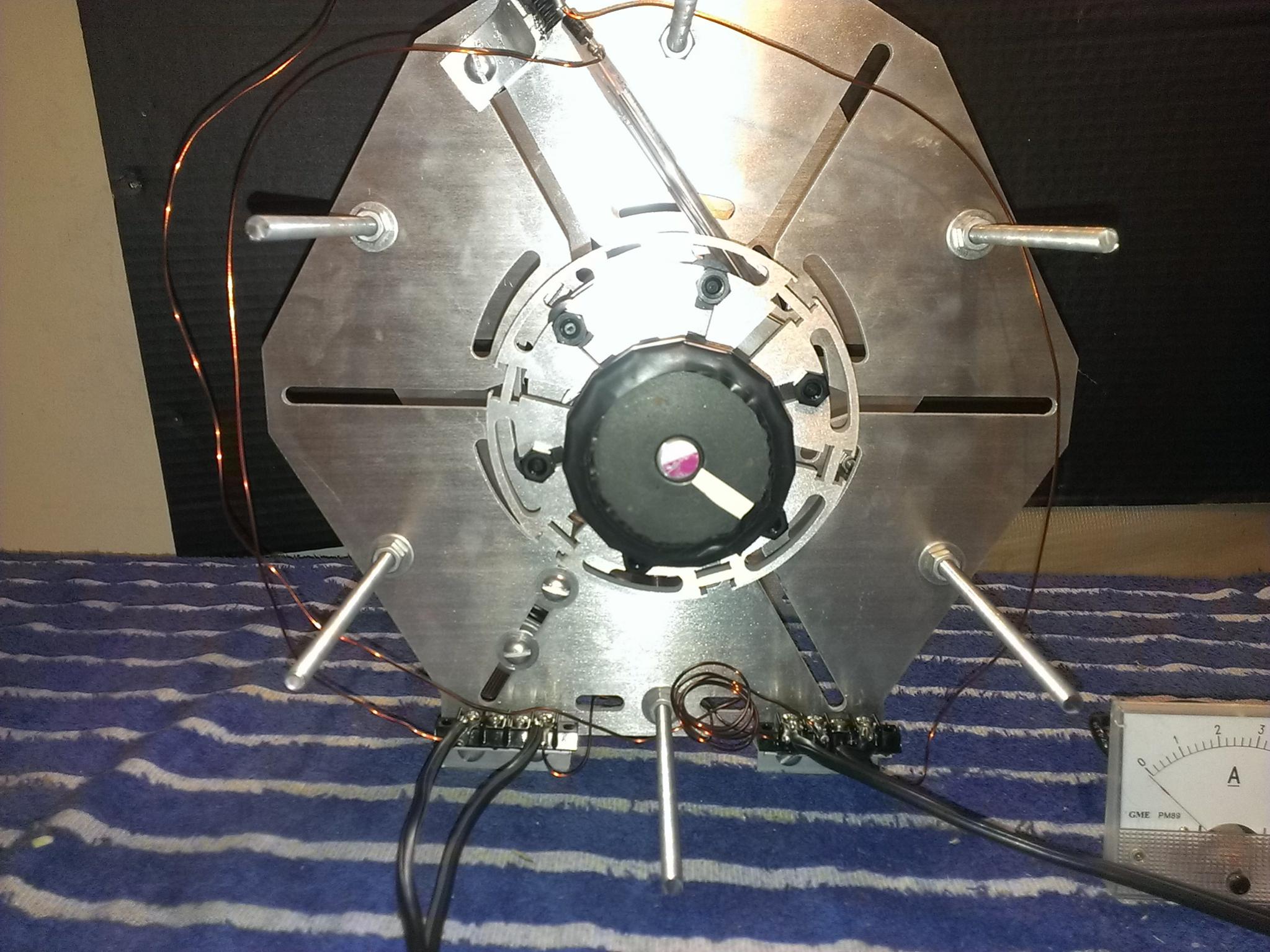
    This machine will not be using transistors for the switching. I have been testing some different methods and I think I have found something that works pretty well. I use welding rods as contacts and some brass pipe which I cut into 1 inch pieces. The brass is mounted on a timing wheel with plastic posts and rubber washers to keep the current isolated from the machine. I know this will wear down but that doesn't bother me since I can just replace the rods as needed. I have only had it running for a day so there is much to learn about it going forward.

    Here are some pictures:

    Click image for larger version

Name:	Clack_1.jpg
Views:	1
Size:	806.0 KB
ID:	51250

    Click image for larger version

Name:	Clack_2.jpg
Views:	1
Size:	940.0 KB
ID:	51251

    Click image for larger version

Name:	Clack_3.jpg
Views:	1
Size:	361.2 KB
ID:	51252

    Questions and comments are most welcome in this thread so feel free. ----Bob

  • #2
    I don't fully understand your switching other than it is a commutator. can you describe it with maybe a couple of scribbles on the photo?

    Tom C


    experimental Kits, chargers and solar trackers

    Comment


    • #3
      Sure Tom maybe this will help.

      The rods both make contact across the brass closing the switch, when the coil pushes the wheel away it opens the switch.

      I am testing right now on one coil. Hopefully tomorrow I will shoot a video and do a run with some charts.

      Click image for larger version

Name:	Clack_4.jpg
Views:	1
Size:	590.0 KB
ID:	47178

      Comment


      • #4
        Hi Guys

        Wow! That looks sharp! I have been meaning to ask this question: has someone, or couldn't someone machine something up to utilize old-style automotive ignition points? They have their own little capacitors to keep the contacts from crusting up quickly, and if one used a GM type, they would be easy to adjust...let me know what you think. John has been hinting that we should be aiming towards figuring out how to use non-electronic triggering. Automotive ignition points are pretty rugged...
        Best Regards ~ James, Somewhere In Idaho

        Comment


        • #5
          Hi James,
          Are you talking about like an old distributor cap style? I like the idea but don't those work from spark gap? I don't think we are playing in a high enough voltage to have it jump but perhaps with some more thought on it there could be a way.

          I have a few reasons for trying to go this way. One of them is simply that transistors, especially matched and all the same kind would be really hard to find and replace in a real extended emergency situation. My largest machine uses 32 transistors and I have replaced them at least four times now from trying different things and messing up.

          Another aspect of this is that the transistor switches very fast BUT I believe that because of the small capacitance in the junction it is a softer switch than a hard break like I am attempting with slap contacts.

          I also just want to experiment with things more as they might have done back in Tesla's days. I have thought about perhaps even getting rid of the diode by making a diode plate with copper and using Mr. Bedini's borax and heat trick as shown with copper magnesium cells. There are things to be re-discovered in using different methods and that is what I am after. For example When I first fired up the new machine it was pulling over 2 amps and I thought hmm ok what the heck can I do to adjust it. Well I could add a resistor to the front of the coil, roll a longer coil or use thinner wire, or what I realized and went with for now was to understand that by changing the length of the bend on my contact I could vary the "on" time. I realized I was on for too long and as soon as I adjusted the shape of the rod I got down to 500ma or so and the charging went WAY up becuse I was now pumping the coil with just enough current and not too much.

          I do think I ned to work on my contacts however. The first set got chewed up pretty fast (picture below). I am now trying a different material, more of a steel rod instead of the welding rod. If this does not last long enough I may try putting some copper on the ends, maybe it will last longer. Anyway this is all about experimenting so expect to see failures as well as success out of me because I do not hide either. I think it is important for us to all share what we try both good and bad so that we can advance collectively.

          Burnt contact:
          Click image for larger version

Name:	Clack_5.jpg
Views:	1
Size:	724.0 KB
ID:	47180

          Comment


          • #6
            Hi BobZilla

            That looks like it is worth a try.

            The way the points style ignition works, is much like the transistor in an energizer circuit. For automotive purposes, there is a coil consisting of transformer with one primary winding and one secondary winding connected to a common positive battery source, with the primary side having a contact set making and breaking a circuit that goes to ground (starting to sound familiar here?). To limit premature failure, the contact set has a small matching capacitor to dampen the current, limiting arcing. A small cam runs the contact set. Timing is affected by adjusting the plate (or distributor in a car) and then locking it down. One must adjust the gap in the contact set first, to make sure they are opening enough to help prevent arcing. In order to have coils firing at different times (like, say, an energizer with a full Bedini-Cole bi-polar switch) one would just place a second contact set at the proper degree difference on the timing plate. Or, if one wanted several separate firing positions on a rotor, just include that many contact sets at appropriate positions. I have attached a PDF showing how one could daisy-chain coils on one contact set. Compare this circuit to a Bedini monopole circuit, and you should see the same similarities I see. You could use the same principals that standard contact sets use to avoid premature failure of your design. However, automotive contact sets may be the answer for replacing reed switches, and rotating commutators, with heavy duty switching for these projects, and use off-the-shelf, cheap (like $2, I think) parts from the local auto parts store. Following is that PDF:
            Last edited by James_Somewhere_In_Idaho; 11-22-2015, 12:42 PM.
            Best Regards ~ James, Somewhere In Idaho

            Comment


            • #7
              James maybe I am missing the point but I keep thinking that the rotor does not touch the distributor cap points (where the switch in the diagram is). As I said before since we are dealing with low voltage I do not see how to make it jump without contact. In a car it arcs through an air gap between the cap and the rotor because of that stepped up transformer/capacitor.

              Now if your talking about using some step up then that would be different but I am only trying to switch 12 or 24 volts because it is really just a short across the source battery and it would quickly destroy the battery to throw high voltage with current back at it.

              I am with you that it seems like a great way to rig something up but I am just not sure how it would be done.

              Comment


              • #8
                Hi BobZilla

                My Bad...having had automotive experience in my youth (had my own shop, and worked on a lot of high performance rigs), my mind just went to assuming everyone has that experience...sorry.

                Ok, let me be more specific: We are not talking about using a distributor, and an automotive coil--just the contact set(s) with corresponding capacitor (specific to that contact set). We would then make a plate (maybe out of plastic) that the contact set could mount to. The plate, then rests on another plate that is stationary, with the motor shaft going through the center, and is attached in such a way, so one could spin, or turn it in a circular motion for timing purposes, and then be locked down--say, for instance with channels cut for bolts to slide through, and when the machine is timed correctly, you simply tighten them to lock it down. The contact set is then actuated by a cam, or lump on the motor shaft. This serves the same purpose as your idea with the copper brushes on a commutator, or reed or hall switches. Then they are hooked into the same coils you were going to originally use--no distributor, no ignition coil...Hope that helps...
                Last edited by James_Somewhere_In_Idaho; 11-22-2015, 06:41 PM.
                Best Regards ~ James, Somewhere In Idaho

                Comment


                • #9
                  Hi Bob and James,

                  Using breaker points would work, but I think using an automotive capacitor across the points would absorb some of the high voltage spike greatly reducing the desired radiant effect. If the energizer coil output is collected in a battery or cap discharge unit, the voltage across the points would be similar to the voltage that appears across a switching transistor wouldn't it? I don't think a cap across the points would even be needed would it?

                  Any form of mechanical switching will be prone to wear and some arcing, so is still not a perfect solution. As far as mechanical switches go, isn't a carbon brush running on a segmented copper commutator about the most reliable?

                  Comment


                  • #10
                    Hi Gary Hammond

                    Good point about the capacitor. Yes, I think you are right.

                    In regard to the commutator and brushes, John B. has stated many times that those run the best. However, the contacts where the brushes move along the commutator roast fairly quickly, then you usually have to build a new commutator. The ignition points idea might not be as "powerful" in regard to output, but they are easy to service. Back in the day, we ran high output coils on muscle cars, and when the points pitted, we could just file them with a file made for that, and then we were literally "back to the races." Plus, they are cheap and still fairly plentiful (at least here in Idaho) so one could buy them in bulk for the zombie apocalypse (saying that with a little snicker, but seriously, might be a good idea) .
                    Best Regards ~ James, Somewhere In Idaho

                    Comment


                    • #11
                      Hey guys,
                      So the other rod I tried seems to be working a bit better. I knew these things would wear as Gary says, it's going to happen. For what it's worth I am using the rod from a ground marker flag, you know like the ones they use to mark water pipes or gas lines. You can get them at any hardware store. Also the welding rods may work better than my first set did because I am figuring out the best angle of attack and the pressure to put on them, all contribute to the wear. Gary I think your probably right that brushes would be best but I am just trying simple things. Eventually I may tear a motor apart and see if I can use some parts.

                      Anyway I have been tinkering all day with it so I didn't get a run in to show. I am going to shoot a little video of this thing in action and let it run a few hours but I don't have time for a full run. I will post a bit later with an introduction video for this new machine.

                      Thanks for all the input guys, will post back a bit later with a video.

                      Comment


                      • #12
                        Hi BobZilla

                        Cool...can't wait to see how it runs.

                        I need to find out how to do the video thing, as my current project is getting close to complete...anyone good at tutoring for videos??? Hook a Bro up???
                        Best Regards ~ James, Somewhere In Idaho

                        Comment


                        • #13
                          Hi James,

                          Originally posted by jamesgray3rd View Post
                          .......... Back in the day, we ran high output coils on muscle cars, and when the points pitted, we could just file them with a file made for that, and then we were literally "back to the races." ...........
                          Yeah I burned up lots of points back in the day. I even went so far as to build a cap discharge unit from plans in a magazine for my '67 Mustang GT with 390 engine.
                          It ran the engine OK but caused the tach to read 5500 RPM at idle, so I didn't use it! That beast could crank 6000 RPM and went through points in about 5000 miles or so. Didn't do much better on tires either.

                          Comment


                          • #14
                            Hi Gary

                            Hahaha! Ya, we did the same things! Some of us even tried big Malory ignition transformers (geese! I think that coil was 3 inches thick by 4 inches wide by 6-7 inches tall--maybe 8) and ran them reverse polarity with a toggle switch...whew! burn them points up! If we only knew...I had a 327 kept busting motor mounts crushing the distributor against the hood, until I put solid mounts on it...my only Ford was a 54 pickup with a 351 and a C-4 tranny I put a shift kit in. Shifted so hard it finally tore the transmission in half...ouch! Anyway, sorry BobZilla, just reminiscing...
                            Best Regards ~ James, Somewhere In Idaho

                            Comment


                            • #15
                              No problem James ;-)

                              I started working on cars just as they were all going over to computerized stuff and injection systems etc. Late 80's cars and beyond but I am no mechanic, just replacing alternators, starters and random parts.

                              So I do have that run underway but the chart is not doing much so far. I may have been a little ambitious, all day I have been messing around on one garden battery and for this run I threw two on there. I think I will let it run over night and see how it looks before heading out to work in the morning.

                              Comment

                              Working...
                              X