Announcement

Collapse
No announcement yet.

Two Stage Mechanical Oscillator Replication

Collapse
X
 
  • Filter
  • Time
  • Show
Clear All
new posts

  • Gary Hammond
    replied
    Hi Michael and Paul,

    Thank you both for the nice comments.

    Just to be sure I understand your previous comment #33, when you added winds to the "genny" coils, the line of vertical coils that the swing arm with its magnet moves past, it braked the wheel so much it would slow down?
    The design was wrong for what we were trying to accomplish with the coils. There were only two coils and four magnets without enough travel to get a flux reversal in the cores in straight line motion. Plus we had the air gap so small trying to boost the voltage that the magnets would sometimes grab the cores and stop the swinging. I robbed that setup from the previous rotating flux gate generator I built to run from my attraction motor. When rotating, it worked very well and gave two flux reversals each revolution. I've now put it back on the attraction motor where it belongs.

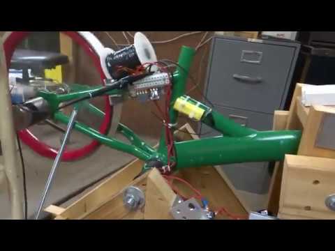
    Another problem was the original SSG drive circuit/coil arrangement wasn't powerful enough to keep the speed steady. There is some mechanical feed back to the wheel from the work end. It's all a delicate balancing act to get it running somewhat steady. And by making a new genny coil setup with six closely spaced coils and seven pairs of magnets, we were able to get flux reversals in the cores every revolution of the wheel. Plus we were able to open up the air gaps to about 3/8" which reduced drag and still gave good output. Flux gate generators require a large air gap.

    The hall triggered FET powering the three power windings, plus the dual recovery circuits, really helped the overall performance of the machine. I had a lot of fun building this with my grandson!

    Leave a comment:


  • ZPDM
    replied
    That is an awesome build Gary! I am very impressed with the workmanship. As I mentioned previously I always wanted to do something like what you did here but wasn't sure if I had the build skills and patience to get such a thing successfully running. Now we know it can be done! Perhaps you sent an e-mail along to Veljko, I bet he would be delighted to see it as well. Just to be sure I understand your previous comment #33, when you added winds to the "genny" coils, the line of vertical coils that the swing arm with its magnet moves past, it braked the wheel so much it would slow down? Again thanks for building this!
    Last edited by ZPDM; 12-30-2019, 02:22 PM.

    Leave a comment:


  • Michael Luton
    replied
    Very good Gary. Its great how you brought the different tech to work together so well.

    Leave a comment:


  • Gary Hammond
    replied
    Hi Yaro,

    Thanks Yaro ............ Kudos to you on your research into the YZFM! I've been following your progress even though I don't comment very often.

    And Happy New Year back at you.

    Leave a comment:


  • Yaro1776
    replied
    Hey Gary,

    Excellent thread demonstrating the progression of the mechanical oscillator project along with the extra additions of the SSG wheel/circuit and flux gate generator for battery charging. All in all a clever and well thought out project. Kudos to you my friend and a salute to your mechanical/electrical skills for making this all happen.

    Happy New Year to you...

    Leave a comment:


  • Gary Hammond
    replied
    Last Update

    Hi All,

    I've spent quite a bit of time making a new 6 coil flux gate generator with 7 magnet pairs. I also beefed up the wooden frame some more and then added some extra length to the swinging magnet arms to get the magnets farther away from the pivot point. A balance weight, two compression springs, and a long tension spring were also needed to give the best results.

    I then modified the coil driver circuit. It uses a hall triggered FET to power all three power windings in parallel to increase the speed, power, and constancy of rotation. The former trigger winding is now used as a power recovery winding using a full wave bridge feeding back to the run battery. I also added a diode and capacitor to feed the radiant spikes to a separate charge battery. The batteries can be switched back and forth while running with a 4PDT switch. So even though the circuit requires 900 ma to operate, the combined energy recovery along with battery swapping reduces the total consumption to a much lower value.

    The new 5.5 AH batteries shown being used in the video are too small and running at a C6 rate. But over a two and a half hour run the two batteries on the front end were showing only a small loss of total charge. And the battery on the back end being charged by the flux gate generator was holding steady at 12.8 volts while powering a 100 ma LED strip.

    Even though this thing is still under unity, it has been a great teaching tool for both me and my grandson. And we did achieve our goal of producing some useful work from the output. I think this device works best as a mechanical oscillator when using the pendulum and extracting slow speed mechanical power off the work end such as encountered when pumping water. I'm now ready to ship it off to my grandson for him to play with and use for show and tell at school.

    Here is a video of the machine running. I misspoke in the video when I said the FET was triggering once per revolution. What I meant to say was it only triggers once per magnet pass. With 14 magnets on the wheel at 100 hertz it figures out at 428 RPM and about 7.14 hertz on the output of the genny coils.

    Last edited by Gary Hammond; 12-14-2019, 01:23 PM.

    Leave a comment:


  • Gary Hammond
    replied
    The two stage oscillator build nearly came to a halt when my grandson took a summer job in construction. And now his school has started again, and he has too heavy of a scholastic load to continue shop class with grandpa.

    One thing we discovered was that whenever we got the wheel up to a speed that would produce the maximum swing of the generator magnets for maximum voltage output, it would produce mechanical feed back that soon slowed the wheel down. Then it would speed back up and repeat the process so that it wouldn't maintain a steady speed. We even added more windings to the genny coils and added a second SSG coil and circuit to drive the wheel. Didn't help very much.

    So now I'm making a new set of genny coils and magnet setup in a different arrangement to see if I can get more output with less drag. No pictures yet. This is going slow as I'm working on it by myself now

    Leave a comment:


  • Faraday88
    replied
    Originally posted by Gary Hammond View Post
    Here's another update. We're getting closer, but still not there yet.

    Great! keep up the spirits high.
    Best Regards,
    Faraday88.

    Leave a comment:


  • Gary Hammond
    replied
    Here's another update. We're getting closer, but still not there yet.

    Leave a comment:


  • ZPDM
    replied
    Awesome stuff

    Leave a comment:


  • Gary Hammond
    replied
    Here's the video. It refused to attach to the previous post.

    Leave a comment:


  • Gary Hammond
    replied
    Hi all,

    Here's an update to our two stage oscillator project. We got the genny coils mounted and checked the output which is pretty low. The wave form is shown in this photo.

    Click image for larger version

Name:	DSC06977.jpg
Views:	1
Size:	966.6 KB
ID:	50190

    The genny coils are shown in this photo.

    Click image for larger version

Name:	DSC06976.jpg
Views:	1
Size:	951.1 KB
ID:	50191

    When the magnets were moved closer to the coils, the frame wasn't rigid enough to keep them from dragging. So we added some stiffeners to the frame and we still need to add a few more.

    The voltage doubling setup gave us about 4 volts DC and would light a string of LED's. We need to get a lot more voltage than this to charge a battery. So we are going to replace the pendulum with a weighted bicycle wheel and try spinning it with an SSG circuit. If this works, we may power it with a split the negative battery rotation scheme.

    When we placed the unit on the concrete floor with the pendulum installed, we had to hold it down as it was bouncing up and down. So however it's driven, it will need to be anchored down securely.

    The video is in the next post.
    Last edited by Gary Hammond; 06-07-2019, 11:55 AM.

    Leave a comment:


  • ZPDM
    replied
    Hi Gary,

    https://www.youtube.com/watch?v=3nik7JyNRbE

    At around 8:32 Veljko starts a discussion of a, "Fast Model with Eccentric Rotor" He notes you can run it at 12,000 RPMs. This two stage oscillator set-up will work with any unbalanced rotor. As energy imparted should increase with square of velocity, I think one issue is just how sturdy is the set-up as by design it will want to tear itself apart with a spinning unbalanced rotor. I suspect, but this is a guess, the lever arm will also only have one behavior with a full rotation, not the two seen with the half swing pendulum set-up. The other cool thing demonstrated in this part of the video which I had forgotten about is he demonstrates no change in amp draw with loading of the lever arm as opposed to loading of the drill bit side. Not wanting to come across as pushy, just mentioning some other things that might be fun to look at at some point.
    Last edited by ZPDM; 05-03-2019, 01:41 PM.

    Leave a comment:


  • Gary Hammond
    replied
    Hi Aaron,

    Originally posted by Aaron Murakami View Post
    .................With 1 SG coil - just put 3 magnets with with spaces between them on the pendulum. It would be like a piece of a wheel with a few magnets. That one coil will go as high as you need. Keep the setup like you have it, just add 2 magnets - one on each side. Make some little retainer to attach to the pendulum and you're done.
    I think this would work great if the pendulum pivot point wasn't moving up and down as the pendulum swings. But if the magnets are spaced 2.5 magnet widths apart, by the time the outside magnets are nearest to the core the whole pendulum pivot is not at it's lowest point. If the magnets are spaced closer together it might not work well either?

    One thing I like about attraction and then repulsion is it assists the pendulum in it's natural movement first toward and then away from it's lowest point as the pivot point moves up and down. It not only assists the swinging, but also assists the up and down effort at the same time.

    The more I think about it, I'm leaning toward the Bedini/Cole bipolar circuit with two separate trigger coils wired in opposite directions.

    But today, my grandson was here for shop class and we discussed everything on this thread so far. We concluded maybe we should change our focus and work out the generator end first to see what is really needed to drive it. We cut the fork tube off the frame and made a bracket to carry the magnets and shunt bars I used previously on the G-field generator I built that was driven by my attraction motor. We are also going to use the coils from that same generator.

    Next week we will weld the magnet assembly to the bicycle frame and mount the coils to the wooden A-frame. Here's a picture of what we got done today. The parts are sitting on my cnc mill waiting to be welded together. The coils are also there for the picture so you can see how it will work.

    Click image for larger version

Name:	DSC06975.jpg
Views:	1
Size:	990.8 KB
ID:	50177

    Leave a comment:


  • Aaron Murakami
    replied
    I mentioned 3 coils and one magnet, with attraction mode, you'd still might not trigger it well.

    With 1 SG coil - just put 3 magnets with with spaces between them on the pendulum. It would be like a piece of a wheel with a few magnets. That one coil will go as high as you need. Keep the setup like you have it, just add 2 magnets - one on each side. Make some little retainer to attach to the pendulum and you're done.

    Leave a comment:

Working...
X