Announcement

Collapse
No announcement yet.

R-Charge Window Motor

Collapse
X
 
  • Filter
  • Time
  • Show
Clear All
new posts

  • R-Charge Window Motor

    Hi

    Thankyou to the people who have helped setup the new forum it looks good and to John Bedini for sharing his knowledge freely.

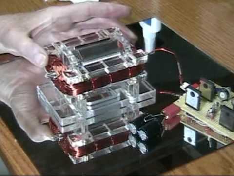
    I have recently purchased a window motor from R-charge it has three larger SSG circuit components and three 19 gauge coils to go with it. One being bifilar. I am waiting on a pot and some resistors so i can tune it. Is anyone else using this kit and if so what amp draw, rpm, battery charge voltage are you getting? Also this kit has come with neo magnets, so im not sure what kind of impact these will have. Also has anyone added the bipolar curcuit to this kit? Or tried to generate some extra power from the shaft of the motor.

    Thanks for your time Wade.

  • #2
    Wade,
    I highly recommend you pursue the bipolar circuit, preferably hall switched, since you only have one trigger winding at the moment. Depending on your skill level and past experience I would proceed as such.

    1. connect SG circuit up to coil (master bifilar only) and get it running. Check that everything is balanced and running smoothly. Tinker and measure its charging ability, but dont get too hung up on that.

    2. replace SG circuit with 1/2 bipolar circuit, use trigger winding to start with. This will only switch on every second magnet, if your rotor is nsnsns. Observe and study circuit function. Its not as straightforward as it may seem at first glance. You can parallel as many strands to the 1/2 switch as you like (within reason). They must be in phase with master coil and of correct polarity.

    3. full bipolar circuit will require hall or optical triggering or another winding or pickup coil. Hall triggering will benefit from a separate timing disc, fixed to the shaft. There really is alot of work to keep you busy in steps 1 and 2. The SG circuit will power this motor, but it was not designed for it, and in my limited past experience I have found the charging in SG mode on the window motor platform to be inferior to the true SG monopole, with cores, as designed by John. But hey, feel free to prove me wrong anyone.

    Most of all, have fun, and learn. The half circuit is so cool. I wish I had started studying it earlier on in my journey. Scaled up correctly the window motor is a beast, better have your thunderware on when you flick the switch on a multi coil multi phase neo magnet window motor. Tom C has a lovely example in the works from memory.

    Regards

    Comment


    • #3
      Hey Ren, How are you? Wow, someone let me on this forum without a promise to be good. But I promise guys. I have been wondering about something regarding the half wave circuit. Does anyone have a good explanation about the values of the resistors used in the circuit? In other words how were the values chosen and how do they effect the operation of the circuit. I'm not referring to the trim resistance. I think most know I like to try running the motors at the lowest amp draw as possible just for fun. At one time I had my window motor running at less than 20 micro amps. The only way I can do this is with the small MPS A06 and 56 with a 2N 2222 driver as well as no resistors in the circuit other than the trim resistor. Just wondering. There's probably a detailed explanation somewhere and I just missed it.
      It's good to be here.
      John H.

      Comment


      • #4
        Ok, I'll take a stab at it

        This is how I see it, and I promise to change my opinion as soon as others type up a more accurate description :-)

        - all 4 resistant points are all about controlling how far each of the 2 "MJL's" doors open.

        The main goal is for the EC of each MJL to open at the exact same time and to allow in (to the coil) the exact same amount of energy simultaneously, then close quickly and simultaneously to allow discharge through the FWBR. Keeping in mind every coil is different and has it's own requirements about how much and how fast you allow the energy in. This allows the efficient charge/discharge of the coil.

        Now I know your question is deeper than that...


        The first resistor to the base of the controlling Transistor from the trigger coil or hall or reed.... as you note, the trim, is the main controller once we set/decide on the other 3.

        The Two EB MJL resistors will simultaneously control their respective EC currents "chicken or the egg" this is where we ultimately control the speed/freq/depth of charge to the power coil.

        The 3rd resistor, that connects the controlling transistor to the pnp, seems to be there to control the balance between the pnp and the npn. I'm guessing on this as my attempts to beta match a pnp and an npn are not very fruitful as much as I can tell, and when I sub in various pnp's or npn's, I have to adjust the resistance here to get the signal back where I want it.

        As usual, I'll be looking forward to more advanced explanations :-)
        Patrick

        Comment


        • #5
          Hey John,

          Great to see you here mate! Im doin ok, recovering from injury so you poor guys have to put up with my ramblings till they let me out of the house. It keeps me sane, but probably drives you INsane lol.

          Woulkd love to flesh out this section of the forum a little more, there are some great replications out there. Yours stands right up the top IMO that tiny little window motor chugging away on almost nothing was so cool. Im not sure about a detailed description. My basic understanding was that the resistors on the E-B of the complimentary pair were there so the triggering transistor was able to pull a small amount of power from the source to complete the triggering, similar to the way a darlington arrangement works I guess. But if you have it running without this then there goes my theory.

          I will say this. Dr Stifflers designs (the ones he released anyway) focus specifically on the MPSa06. He said his effect was more pronounced with this transistor alone, he was unable to find any others that worked as good. He went into the actual specifics as to why, from what I gathered it was the way it was made. I find it no surprise that John B also selected this transistor.

          Also the 2n2222 is a funny little guy who exhibits some useful qualities, he is often used in touch sensitive circuits, because he can be setup so that simply touching the base with your hand can trigger the circuit into operation.

          Look forward to any other comments.

          Good to have you here DadHav

          Regards

          Comment


          • #6
            Resistors

            Hello Patrick, Ren.
            I hear what your both saying. It's just that there may be some simple things we are missing. It's not clear to me what is really going on with matching transistors I guess. I can test the gain and match a set pretty close, but if the gain is identical does that mean each of the transistors will come on at exactly the same voltage and reach saturation at the same voltage? I think I read that JB wanted the PNP of the half wave to turn on first, but I don't remember. If that's the case more resistance on the NPN could probably do that, but then the gain relationship between the two would be uneven through the curve no? I'm sure the theory of timing, gain, saturation etc. are all covered but I just missed it somewhere. I've mentioned this before but out of a batch of 50 MPSA 06's I had one in a small SSG that seemed at the time to have about 5 times the charge characteristics than the rest. I was so excited that I blew the transistor from being careless. Like so many things I've experienced, sometimes you can't duplicate results once you break a setup and start again. Ren, Thanks for the compliment on the window motor. I just had someone call it a fish bowl and another a plastic toy. There is something I never posted a video on and that's how strong that motor runs at less than .5 amps. If I ever have another video with it I'll through a radiator fan on it of something.
            Take care guys. It's good to talk to you.
            John H.

            Comment


            • #7
              Right back "atcha" John H. - some excellent questions, and right to the point.

              My main thought was that the pnp and npn IMHO do not need to be "perfectly" matched, and that the ckt takes care of their "small" differences - however if we are paralleling transistors as JB does on the Ferris Wheel, and/or are using the "full bipolar switch", we will need to match the row of npn's to npn's and pnp's to pnp's - or we will create heat, the thief we seek to avoid.

              Now, there is more to a transistor than I can hope to know, all I know is there is more I need to learn... even the question you bring up sheds new light..."the gain relationship between the two would be uneven through the curve" could this be the reason for the 3rd resistor/pot? I find there is a very small window when tuning this 3rd resistance where the charging takes off....

              John Bedini, I would love to hear some insights on this subject as well... Please :-)


              Sincerely,
              Patrick

              Comment


              • #8
                Hi Patrick. I guess what I'm wondering is why no resistors seems to work better for me in the low current and voltage range. A simple answer may be there is less voltage dropped across components in the circuit, so the coils get a little more potential. I hate to bother John, I know how busy he must be. I just thought it was an interesting thing to talk about. Although I might be tempted to build a little larger if I thought I understood enough to come up with better results than what I currently have.
                Thanks Patrick.
                John H.

                Comment


                • #9
                  DadHav,
                  So just bother me that is why I started this board.
                  First let me say that some of you remember Carl Hurst from the old window group. Most of the Window Motors Rick has changed to his design by putting the coils on the outside and that is not the same window motors Ron Cole and I built, as the fields are much differnt. But they all use the same circuits for recovery. But anyway what do you want me to help with?
                  John B
                  John Bedini
                  My homepage: http://johnbedini.net

                  Comment


                  • #10
                    Hello John, I think this is probably the first time we've talked. I've had some really good results with running the window motor from capacitors. I've used the small MPS A06 and 56 complimentary pair with a 2N 2222 driver both in the half wave and full wave circuit. I have very good results with only trim resistors in the circuit and have been able to run the window motor at less than 50 micro amp average. My question was related to what the resistors in the half or full wave standard circuit are doing and what determination was associated with their values. I'm referring to the 470 ohm resistors between the base and emitters of the power transistors and the 220 ohm resistor from the emitter of the driver transistor to the base of the PNP power transistor. I was also wondering how the individual gains on the transistors effect operation of the circuit. I thought I remembered you saying you preferred a delay on one of the power transistors. I hope this wasn't a lame question John. I appreciate you taking the time to look into what we where talking a about.
                    John H.

                    Comment


                    • #11
                      Originally posted by DadHav View Post
                      Hello John, I think this is probably the first time we've talked. I've had some really good results with running the window motor from capacitors. I've used the small MPS A06 and 56 complimentary pair with a 2N 2222 driver both in the half wave and full wave circuit. I have very good results with only trim resistors in the circuit and have been able to run the window motor at less than 50 micro amp average. My question was related to what the resistors in the half or full wave standard circuit are doing and what determination was associated with their values. I'm referring to the 470 ohm resistors between the base and emitters of the power transistors and the 220 ohm resistor from the emitter of the driver transistor to the base of the PNP power transistor. I was also wondering how the individual gains on the transistors effect operation of the circuit. I thought I remembered you saying you preferred a delay on one of the power transistors. I hope this wasn't a lame question John. I appreciate you taking the time to look into what we where talking a about.
                      John H.
                      Just for reference here is some of Dadhavs work.


                      Dadhav, you used to have another video of it running on next to nothing, you were measuring the voltage on the cap to 4 or 5 decimal places before you could see the fluctuations if I remember correctly. Was that the 1/2 circuit you refer to above (MPS/2n2222 combo) that had no resistors except in the trigger? EDIT: I found it, its "Window motor assembly.."


                      Regards
                      Last edited by Ren; 08-08-2012, 03:39 PM.

                      Comment


                      • #12
                        Hello Ren, I haven't looked at that video in a long time but when I did I saw a link on it to an update where I took the motor apart to show how it was made but I did have a 5 diget meter reading with the little transistors and no resistors except trim. I think the most I ever ran with so little was on the video Window Motor Runs Window Motor. I used all little transistors with bipolar circuits and no resistors other than trim. I took the output from a notch rotor WM and doubled the voltage by adding the spare trigger coil in series with the power coil. Then I ran the second larger WM at almost twice the voltage. I took the output from the second WM and ran an LED from it. All this was from what I learned from John B, and to top it off I was running everything from a single copper magnesium cell that I learned from John's early crystal battery research. I'm not here to showcase my videos but if you are interested in luck I've had with the little transistors then this would be the video to watch:
                        Window Motor Runs Window Motor. - YouTube
                        I often look back at this video and wonder why I didn't persue this further. I almost don't believe it myself. I must have accidentally come close to getting what John has been trying to explain.
                        John Hav. I see there's another John H. on the forum so I'll use the first letters of my last name now.

                        Comment


                        • #13
                          R-Charge does not know my work

                          DadHav,
                          The 470 Ohm resistors are in the circuit to make sure the base emitter circuit turn off. The circuit was taken from a full Complementary Symmetry Amplifier Ron and I built ( Class B) . You always drive the load in this circuit from the collectors, because of the impedance of the coils. however for power you must build the circuit using Darlington on the PNP side and the NPN side. The full wave bridge is directly across the collectors of the N and The P device, or the Coil. The circuit is arranged to isolate the power supply BEMF is routed to the capacitor and then returned to the battery, for extended run time. If you charge the capacitor and pulse the primary battery the motor must be completely off and then Joules are important stored in the capacitor but you must be at double the battery voltage for the pulse dis-charge to either the primary battery or the secondary battery. You must look at this circuit as an amplifier . People for some reason do not see this, the same applies with the SG circuit. The coil in the circuit is an impedance and it must be calculated that way in terms of gain to the circuits, and that gain is applied to the battery, impedance wise. I think people are missing the point of what the circuit really is, if you wind 3 coils together on the same form, they are all independent charging circuits, think about what I just said here.
                          The BEMF is much lower then the battery voltage, so the spike is charging the cap in time, so time charging. I do know your work and it is excellent, AAA+John Bedini
                          Last edited by John_Bedini; 08-09-2012, 09:49 PM. Reason: corecction
                          John Bedini
                          My homepage: http://johnbedini.net

                          Comment


                          • #14
                            John. Thank you, the compliment means a lot to me. I do remember some things about the difference between class AB and B also remember emitter resistors had something to do with distortion at crossover between the NPN and PNP. I just didn't make that association until you mentioned making sure the transistors turned off. I'll have to read up on that a little bit to freshen my memory. I think I'm getting the the point you're making. Thanks I'll change my mind a little about what I'm doing.
                            Thanks again
                            John Hav

                            Comment


                            • #15
                              Originally posted by John_Bedini View Post
                              The coil in the circuit is an impedance and it must be calculated that way in terms of gain to the circuits, and that gain is applied to the battery, impedance wise. I think people are missing the point of what the circuit really is, if you wind 3 coils together on the same form, they are all independent charging circuits, think about what I just said here.


                              John K.

                              Comment

                              Working...
                              X