Announcement

Collapse
No announcement yet.

ZFM Advanced Explorations Part II

Collapse
X
 
  • Filter
  • Time
  • Show
Clear All
new posts

  • Yaro1776
    replied
    ZFM 6 Pole with Stacked Neo's

    The testing program for this season has come to completion with the 6 Pole rotor outfitted with one set of six 2"x0.75"x0.375" Neo's stacked with 1.5"x0.75"x0.188" Neo's using the Loctite AA 326 magnet adhesive. The Neo's were first stacked and cured, then mounted very carefully on the rotor taking into account the nearly 80# pull force. Fortunately the Al rotor is non magnetic, however the adjoining magnets make this a somewhat tricky operation.

    Click image for larger version  Name:	IMG_1698.JPG Views:	0 Size:	98.7 KB ID:	72786

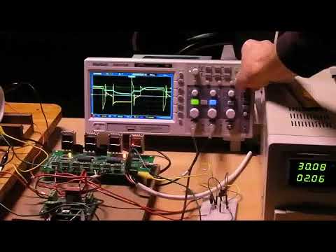
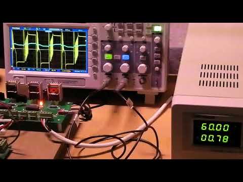
    The rotor was installed in the 3 coil ZFM assembly with the coil to Neo gap adjusted to 1/16" - tight. The ZFM was then tuned to the appropriate dwell and advance, then cranked up and tested both in serial and parallel mode. The longer length and greater magnetic pull force along with the tighter gap over the previous configuration did reduce the RPM, but improved the overall efficiency. The most reasonable configuration that yielded both output power and efficiency was in the 30 volt parallel mode. The virtual coil poles for this Neo arrangement were very similar to the prior posts coming in about 55 degrees - not ideal but close to. So lets take a look at the run data:
    RPM Load(gr) Output(w) Volts Amps Input(w) Eff%
    4026 0 0.00 30.28 0.60 18.17 0.00
    3406 1020 22.61 30.66 1.39 42.62 53.06
    3010 1630 31.94 30.64 2.03 62.20 51.34
    2917 1825 34.65 30.72 2.16 66.36 52.22
    2942 1760 33.70 30.66 2.14 65.61 51.37
    3402 960 21.26 30.31 1.40 42.43 50.10
    So the modifications demonstrate that improvements can be gained in performance. Further improvements can be gained by several methods: 1) Virtual coil arc of nearly 60 degrees, 2) Improving the actual coil dimensions to a tighter tolerance for consistency and 3) Better selection of Neo sizing.

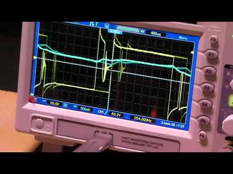
    A quick expanded look at the oscope shot at high load below

    Click image for larger version  Name:	pic_228_7.jpg Views:	0 Size:	120.0 KB ID:	72788

    One will note how quickly the amperage (blue trace) returns to a zero value when the power is cycled off and the how rapidly the voltage rises on power-up - a definite characteristic of the air coil. So at this stage of experimentation all the goals were achieved, with the exception of the virtual coil arc. This particular ZFM configuration should be able to achieve 60% efficiency or more with the proper build techniques and tuning.

    For the next phase of evolution there are experiments planned to work with the coil wiring using a multifilar approach. A recently conducted experiment using the current assembly yielded preliminary results demonstrating that this can be a very worthwhile direction. More to come this late summer barring any disruptions in the material supply chain. One can only hope!

    Thank you for your attention, stay healthy and enjoy the summer,
    Yaro
    Attached Files
    Last edited by Yaro1776; 04-27-2020, 10:27 AM.

    Leave a comment:


  • Yaro1776
    replied
    ZFM Video 20.4 6 Pole

    So the next rotor configuration was designed to further explore the displaced magnetic poles of the coil. The static arc width of the individual coil poles was set to 560 by increasing the width of the Neo's to 0.75", unfortunately the Neo lengths and thicknesses available for this width are very limited. As a compromise the length was set at 1.5", a bit shorter than the rotor length of 2", with a coil to Neo gap of 0.130" +/-. Not ideal but useful nevertheless for exploring.

    So the coil arc dimension is 450 and the Neo's are separated by an arc of 600. So there remains a bit of play here that needs to be considered. That is the fun part and the most tedious to explore. For this config the overall length of the coil power on period is 490 taken directly from the screen shot. This value can be expanded or contracted a bit by the positioning of the reed mount with respect to the timing rotor face. The start of the power-on pulse (advance) can be controlled by rotating the reed mount cylinder.

    Since the coil's magnetic poles function in a simultaneous push/pull manner on the 6 pole rotor the coil magnetic pole arc value becomes very important. One can design for the static configuration, but does this hold true dynamic operation? Good question...

    Anyway, for the video the ZFM was operated at 48v to demonstrate the major point - BEMF value and its influence. By nature, adding more Neo's and coils for a given design will increase the BEMF. For this config the peak BEMF is typically ~15% higher than the input voltage at unloaded speeds. Reducing the number of rotor poles and motor coils will reduce the BEMF value for a given RPM. The reverse is true also.


    The load for the video was 1400 gr. yielding 25.5 watts or 18.8 ft lbs/sec of useful power at an efficiency of 46-47%.

    Changing the wiring from series to parallel mode at 24v yields nearly identical results.

    Yaro

    Leave a comment:


  • Yaro1776
    replied
    Originally posted by John_Koorn View Post
    Great to see you're still at it Yaro
    Thanks for the encouragement John!

    Not done with this motor as yet and am preparing another rotor design for the 6 Pole. I expect to put this modification into testing shortly with the goal being an efficiency of 60% under load while staying within the dimensional constraints of the existing motor body and three coll config for the 6 Pole.

    The virtual pole concept for the air core coils is still in play...
    Yaro

    Leave a comment:


  • John_Koorn
    replied
    Great to see you're still at it Yaro

    Leave a comment:


  • Yaro1776
    replied
    ZFM Video - 6 Pole in Parallel

    To finish the documentation on the parallel mode of operation for this rotor (2"Lx1/2"Wx1/2"T) the following video was completed to flesh out the information.

    The setup was the normal arrangement with the exception of the individual coils being wired in parallel and then connected in series. Parallel mode compresses the operation by reducing the voltage required to drive a load at a desired low usable RPM. Very useful for the lower RPM range in that it can be a direct drive type of arrangement for transmitting power; powered either through a solar panel or LAB. The nominal power efficiency throughout the test was 50%+/-.

    RPM Volts Amps Load gr %Eff
    4182 24.08 0.57 0 0.0
    3350 24.42 1.37 800 52.1
    2550 24.98 2.02 1400 46.1
    5186 30.18 0.69 0 0.0
    3343 30.03 2.03 1400 49.5
    6014 36.03 0.77 0 0.0
    4167 35.99 1.99 1400 52.7
    I may add some more info to this post later, but ready to move on...

    Yaro Happy Valentines Day
    Last edited by Yaro1776; 02-15-2020, 05:18 AM. Reason: Added Data Table

    Leave a comment:


  • Yaro1776
    replied
    Yo Dennis,

    Thanks for the reply and your suggestions are in mind. This particular 6 pole rotor config has been operated up to 60v in series mode - it is a bit of a monster at this voltage and it yields comparable efficiencies, but the limits of the torque testing apparatus are pushed. In parallel mode the apparent voltage and amperage are magnified by a factor of two or so

    In parallel mode the highest voltage has been limited by the LAB's at 24 volts. The BEMF circuit in its present config has its voltage limitations. I can use the 60v power supply but the motor operation is not as smooth as with the LAB's. In the past the parallel coil circuit has been pushed to 36v with comparable results, but the coils start to overheat due to the higher amperage draw. There is a give and take here that imposes limitations inherent to the coil design parameters.

    I will give it a shot this coming week using the power supply to jack up the voltage in parallel mode. Better yet, build your own ZFM and play to your heart's satisfaction.

    Later,
    Yaro

    Leave a comment:


  • dennis foyil
    replied
    Great report ,Yaro. Looking forward to anything about the 60v results. thanks

    Leave a comment:


  • Yaro1776
    replied
    6 Pole ZFM with Coils in Parallel

    Completing the test program of the 6 Pole ZFM was a series of experiments with the bifilar coils wired in a parallel configuration versus the prior Post's series configuration. The overall three coil parallel resistance was 1.5 ohms compared to 6.0 ohms for the prior series arrangement. The parallel configuration was tested with and without the BEMF recovery circuit and with the 60v Power supply and 24v LABs for comparison. Only the 24v data will be presented at this time.

    The coils in parallel create a different mode of ZFM operation. The amperage draw is nearly double the series mode value for a given run voltage, while the RPM is also nearly twice the series value. The impression is that the motor is running at a much higher voltage. All in all, this mode creates a very tractable motor for certain applications with power efficiencies very close to or at 50%. The 4 Pole ZFM will display similar characteristics when properly configured in parallel mode.

    Below is a sample of the data points for both options. The ZFM has slightly different characteristics between the two types of applied power - the LAB runs required a timing adjustment to compensate. The attached pics were all generated under no Load. Pic 2 demonstrates the oscope wave form for the LAB without the BEMF circuit, while Pic 3 with the BEMF circuit engaged. The Power supply mode with the BEMF circuit engaged is nearly identical to Pic 3 and not included.

    Parallel Mode with Power Supply no BEMF Circuit (Pic 1)
    4360 RPM 24.01v 0.60A 0gr Load
    3234 RPM 24.40v 1.46A 800gr Load 47.3% Eff
    2662 RPM 24.29v 2.12A 1350gr Load 44.5% Eff

    Parallel Mode with LAB and BEMF Circuit (Pic 2 and 3))
    4640 RPM 24.88v 0.65A 0gr Load
    3616 RPM 24.71v 1.52A 800gr Load 50.1% Eff
    2825 RPM 24.64v 2.22A 1400gr Load 47.1% Eff

    Pretty much done with this particular 6 Pole rotor after achieving all the initial design goals and ready to move on to the next phase.

    Pic1
    Click image for larger version

Name:	pic_174_2.JPG
Views:	471
Size:	108.4 KB
ID:	72560

    Pic 2
    Click image for larger version

Name:	pic_174_5.JPG
Views:	446
Size:	109.2 KB
ID:	72561

    Pic 3
    Click image for larger version

Name:	pic_174_4.JPG
Views:	429
Size:	108.5 KB
ID:	72562

    Leave a comment:


  • Yaro1776
    replied
    6 Pole ZFM with BEMF Circuit

    The last experiment in this series was to operate the 6 pole configuration with the Cole BEMF circuit in conjunction 24v LAB for power. The diagram for this circuit is below:
    The BEMF circuit was attached to the coil power input and the BEMF circuit output was wired directly to the incoming 24v power leads. The ZFM was powered up and operated at the 24v provided by the LAB's with the following loads: 0gr, 775gr and 1460gr.

    This data was then plugged into the spreadsheet and the values compared to a prior run without the BEMF circuit:
    With BEMF Circuit (LAB)
    2384 RPM 25.14v at 0.29A ; 0gr Load
    1711 RPM 25.11v at 0.75A; 775gr Load 46% Eff.
    1201 RPM 24.99v at 1.14A; 1460gr Load 40% Eff

    Without BEMF Circuit (Power Supply)
    2304 RPM 24.21v at 0.31A; 0gr Load
    1535 RPM 24.26v at 0.74A; 775gr Load 43%Eff
    1060 RPM 24.45v at 1.17A; 1460gr Load 35%Eff

    The above does demonstrate that the circuit is a positive addition to the 6 Pole due to the high level of induced voltage. Furthermore this can be viewed graphically in the below pics. First pic demonstrates the smoothing action by the circuit. The second depicts the BEMF wave without smoothing on power down - a 60v pic was used for the sake of wave clarity. There is a third pic that depicts 60v operation without the recovery circuit.

    Yaro
    Last edited by Yaro1776; 01-18-2020, 12:56 PM. Reason: Language clarity

    Leave a comment:


  • Yaro1776
    replied
    Maximum Torque at 24v

    Hello to all,

    Things were slowed down a bit due to a bearing failure, but that has been corrected and deemed good. The subsequent experiments have been centered around a beefed up torque testing apparatus and this has allowed pushing the limit up to 1450 grams - nearly double the previous maximum.

    The acid test here was to cold start the 6 pole ZFM at 24v nominal in a loaded condition (1450 gr) and this was easily accomplished yielding a speed of 1060 RPM at 1.17A. The no load speed at this voltage was 2304 RPM at 0.31A.

    This clearly demonstrates the low speed torque capability of the 6 pole configuration. This load value is perhaps the maximum for this voltage's torque curve - overall efficiency dropped off from a nominal 45% to under 35%. The other voltages (36, 48, 60) were not impacted and continued to operate in the 45% efficiency mode under this load.

    The last item on the agenda for this particular rotor config is to plug in the BEMF circuit and see how the collected wasted energy impacts the performance of this machine. The 6 pole configuration has significantly more BEMF than the 4 pole motor - this can be observed at the end of the last video in the prior post. More on this in the next post.

    The 4 pole design is still very worthwhile for higher speed operation and it does have very good torque. One does have to bear in mind that the fruits of the 4 pole experimentation have been applied to this 6 pole config. A new build of the 4 pole, based on this prior experience, should also yield results that are comparable.

    The new forum format works well for me - thanks Aaron!

    Over and out for now!
    Yaro


    Leave a comment:


  • Yaro1776
    replied
    6 Pole ZFM with 6 Neo's Video Run

    Hello to All,

    Finally put together the first public video of the 6 pole rotor with all the Neo's in place. This motor does run strong and for the video a load of 770 grams was used throughout the experiment as a constant load factor for voltages from 24v to 60v in 12v increments.


    Inadvertently a few data points in the video were omitted; included are the nominal voltages for the experiment:

    2032 RPM 24.0v 0.22A No Load
    1550 RPM 24.0v 0.52A w/ Load
    2360 RPM 36.0v 0.65A w/ Load
    3064 RPM 48.0v 0.73A w/ Load
    3840 RPM 60.0v 0.78A w/ Load
    4690 RPM 60.0v 0.43A No Load

    It appears that this particular ZFM configuration has been tuned relatively close to its limits, but early days as yet. The overall efficiency comes in around 45% with several data points over 50%. This does show the inherent potential of the 6 Pole ZFM as a direct drive motor over a wide range of voltages.

    The intention here is to add the spike recovery circuit to the configuration in the near future once all the necessary LAB's are collected and charged.

    There is more, but the video process required numerous takes due to technical gremlins. More than enough for now!

    Thank you for your attention and Happy New Year.
    Last edited by Yaro1776; 01-31-2020, 02:28 PM. Reason: Data Table Clarity

    Leave a comment:


  • Aaron Murakami
    replied
    Merry Christmas Yaro, thanks for sharing - 45%! That's over double the original 20% from the other variations so definitely moving in the right direction!

    Leave a comment:


  • Yaro1776
    replied
    Taming the 6 Pole Beast

    Happy Christmas to all,

    A quick up date on progress for the 6 Pole ZFM. Most of the past week has been spent working with the ZFM timing and getting the machine to perform such that it be ready for prime time.

    The current timing method with the reed switches does work well enough to make this motor perform and it does demonstrate that the 6 Pole is a different Beast of the ZFM family. It is a low speed motor in comparison to the 4 Pole and with very good torque over a wide range. The torque is such that the existing Torque device is not adequate to measure the maximum torque at higher than the 1000gr levels.

    The timing is a bit touchy/sensitive, but can be worked to provide good and consistent data. It has been operated up to 6000+ RPM and 48volt, and it can easily be pushed up to 60 volts to expand the torque curve.

    Best efficiency to date with the current config has been 45%, and perhaps the 50% barrier may be achieved over the next several days - wait and see on this.

    Ready to present a video of the 6 Pole beasty shortly. Ho! Ho! Ho!
    Last edited by Yaro1776; 01-31-2020, 02:26 PM.

    Leave a comment:


  • Yaro1776
    replied
    Further Experimental Data for Two Neo 6 Pole

    Well, I could not leave this 2x1/2x1/2 config alone and decided to torque test it just to say it was done.

    The last torque test for this config demonstrated that for a 2 pole it is pretty gutsy. It is capable of starting under load from a rest position with 550 grams of weight and accelerating to 2410 RPM at 37.01v at 1.69A. It was not pushed! Plenty of low end torque and it gets up to speed rapidly with this load. There still remains the sense that the machine is fighting itself due to the extended firing duration of over 50 degrees. There is a ways to go for an improvement in performance.

    Ancient history for now that the rotor has been updated to to the full complement of 6 Neo's with the new timing duration of about 42 degrees, though a bit under the target powered duration. Nevertheless, ready to be installed on 12/20/19 after the obligatory fiberglass wrapping tape procedure. Pic of the new fashion Rotor:

    Click image for larger version

Name:	IMG_1684-1.JPG
Views:	1
Size:	123.6 KB
ID:	50286

    The assembly procedure used here was to clamp the rotor in a vice and use a pair of wood clamps to handle the Neo's for assembly - a much safer procedure than using the fingers. Used an AA 326 Adhesive (Loctite) with an SF 7649 Primer yielding a rapid cure to full strength. Low odor and readily available versus the AA 332 adhesive, but with about 75% of total strength. Let's see how this works out as the experiment progresses.

    Pic of rotor with Mag Film:

    Click image for larger version

Name:	IMG_1685.JPG
Views:	1
Size:	132.2 KB
ID:	50287

    In closing, the other bigger rotor performed up to expectation, but more definitive data may be posted after a new rotor design has been machined and tested. That may be a ways out based on the shop's work load and available design time.

    Season's Greetings and Happy Holidays from the back hills of Vermont.
    Last edited by Yaro1776; 12-20-2019, 05:27 PM.

    Leave a comment:


  • Joster
    replied
    Most excellent work Yaro as always. That is the nicest Bedini Cole Switch PCB I have ever seen. Looking forward to more updates!

    Leave a comment:

Working...
X