Announcement

Collapse
No announcement yet.

ZFM Advanced Explorations Part II

Collapse
X
 
  • Filter
  • Time
  • Show
Clear All
new posts

  • Yaro1776
    replied
    First Run 6 Pole YZFM w/ Two Opposing N-S Neo's

    After all the trials and speed bumps the 6 Pole ZFM was assembled this past weekend. It took a number of hours to properly align everything and to get the timing as close as the Reed switch method allows. Not perfect as yet...

    The motor accelerates well for a 2 out of 6 Neo config and the low RPM torque is fairly robust. The bare two finger toque test manages to heat up the finger tips rapidly. All of this is just the beginning of another most excellent adventure.

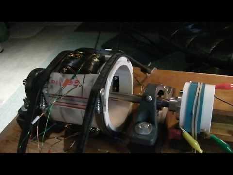
    So for the video the basic operating parameters are 30.24 volts at 1.15 Amps with 3980 RPM.


    The motor is still being broken in and needs a bit of run time. The expectation is that it will work easily up to 48 volts in these initial trials. The timing/coil arc does need a bit of work to fully develop the potential power capabilities, however this will be for a later date.

    Next step is to do a number of trials with the other twin Neo 1"X1"x3/4" rotor. After removing the first rotor the additional 4 Neo's (2"x1/2"x1/2") will be glued to it and cured. Need to observe how the bigger (1"x1"x3/4") Neo's operate with the 60 degree coil pole displacement. Right now the coil pole arc is at 52 degrees with the smaller Neo's.

    Thanks for your attention.

    Leave a comment:


  • Yaro1776
    replied
    Dave,

    Thanks for the lead on the Uber strapping tape. Checked out the url and it appears worthy of a trial. As the rotors increase in diameter and the Neo's become bigger every little bit of extra retention helps. The Neo's skin usually fails first!

    Leave a comment:


  • Dave Wing
    replied
    Originally posted by Yaro1776 View Post
    Thanks for the concern Dennis and Aaron.

    The dry Neo assembly was done to check the fits and forces involved on the rotor prior to applying the adhesive. The rotor was not in the motor and this was part of figuring out the proper Neo mounting sequence. The adhesive will lock everything in place with the strapping tape as a backup - standard procedure in these parts for operation between 6,000-10,000 RPM.
    When it comes to strapping tape this stuff is the best I have found and it can be picked up most anywhere. I have never thrown a magnet when using this tape. http://www.bunkerincorp.com/hurricane.htm

    I hear some of you guys have issues with throwing magnets at high rpm, this tape will prevent that unsafe event from happening period. Run as much tape as your air gap will allow, make sure each wrap around the rotor is applied under tension so each consecutive wrap will apply more compression, holding your magnets tighter to the rotor. You want close to an 1/16th of an inch for wrap thickness when the rotor is taped. Do this and you can run any rpm you want on smaller machines like the ones on this thread.

    Dave Wing
    Last edited by Dave Wing; 12-11-2019, 04:36 AM.

    Leave a comment:


  • Yaro1776
    replied
    6 Pole First Spin

    Another day in the continuing adventure of the 6 Pole ZFM started with mounting two opposing N-S Neo's on the rotor. Rotor was then installed to check the overall pole displacement for each coil. The Neo's are 2"Lx1/2"Wx1/2"T. A certain amount of anticipation here.

    Well, as it turns out the coil pole displacement of 60 degrees was not achieved, only 55 degrees - Bummer! It appears that the longer Neo's, with the 1/2" width, behave a bit differently on the 45 degree coil than the 1"x1"x5/8" Neo's. Certainly, there are other influences that modify the coil pole positions.

    No matter - time for the spin test; the motor was wired up and then powered up at a conservative 12v for the first trial. No problem starting up and rotating at a couple of thousand RPM. Shutdown at this point to assess the successes and failures before going forward.

    Another, more thorough calibration, will be completed within a week and the coil positioning tweaked a bit more based on the calibration data. The intention here is to test this present configuration to establish some initial performance baselines. The coils will be rewound at a later date to adjust for the 5 degrees, however another 6 pole rotor with 2"L Neo's will be tried prior to this modification.

    More pics and a video in the next posts.
    Last edited by Yaro1776; 01-31-2020, 12:52 PM. Reason: Language

    Leave a comment:


  • Yaro1776
    replied
    Originally posted by dennis foyil View Post
    Yaro, Sincerely, consider bolting those in place along with the epoxy. The neos that is. regards, dennis
    Thanks for the concern Dennis and Aaron.

    The dry Neo assembly was done to check the fits and forces involved on the rotor prior to applying the adhesive. The rotor was not in the motor and this was part of figuring out the proper Neo mounting sequence. The adhesive will lock everything in place with the strapping tape as a backup - standard procedure in these parts for operation between 6,000-10,000 RPM.

    Leave a comment:


  • Aaron Murakami
    replied
    Originally posted by dennis foyil View Post
    Yaro, Sincerely, consider bolting those in place along with the epoxy. The neos that is. regards, dennis
    Strapping tape works well - both Peter and John used that on top of gluing the magnets.

    Leave a comment:


  • dennis foyil
    replied
    Yaro, Sincerely, consider bolting those in place along with the epoxy. The neos that is. regards, dennis

    Leave a comment:


  • Yaro1776
    replied
    6 Pole Phase 2

    The machine shop came through with the motor parts today. The parts completed were the Timing rotor and the 6 Pole Neo rotor. Tried a dry assembly of the Neo magnet components along with a steel rod through the center of motor rotor as a magnetic assist. All was good until the placement of the last Neo, then the rotor assembly flew apart damaging two of the Neo's and ending up with two groups of high strength Neo's clustered together. Put this on the Not to Do List, for sure. Separating this mess was tedious.

    Click image for larger version

Name:	IMG_1677.JPG
Views:	1
Size:	98.1 KB
ID:	50254

    For attaching the Neo's to the Aluminum rotor a Loctite AA 332 adhesive will be used. This works well, the Neo skin fails before the adhesive. Game plan is to assemble the rotor step by step and use my Weber grill to cure the rotor adhesive at 200F, fact of life when the outside ambient is less than 20F. Indoors the odor from this adhesive can be toxic, never mind the smell.

    You will note that the Timing rotor has three sets of holes 120 degrees apart for the 1/4"D mini Neo's. In combination with Reed switches spaced 180 degrees apart, the BP switch board will fire every 60 degrees. Of course the appropriate timing Neo's selection must be in place for this to happen. Another obstacle!

    Remains to be seen how all this works out - just an experiment with displaced air core coil poles.

    Ho! Ho! Ho!

    Leave a comment:


  • Yaro1776
    replied
    6 Pole Virtual 60 Degree Poles

    Hello to all,

    Prolonged tweaking and calibration of the the 6 pole ZFM motor has resulted in the virtual pole positions to be all very close to the desired 60 degree arc angle. So all the preliminary experiments have been verified in that all three of the 45 degree coils mounted in the motor body have produced 6 virtual poles that are very close to 60 degrees apart. Very cool to work this progression from concept to actuality.

    Experimental results have shown that the Neo positions and configuration do impact the magnetic pole field interaction with the coil end poles. A N-N Neo configuration is different from a N-S at least for the 2 pole experiments. A series of 2 pole experiments were conducted about a year and a half ago with N-S Neo config and 90 degree coils. These experiments yielded some unusual results which can now be mostly attributed to the expanded arc of the virtual poles. Who knew...

    Moving on, the initial design for this 6 pole rotor called for 2"Lx1"Wx1/2"T N52 Neo's. The physical constraints of the motor body yielded a 6 pole rotor where the edges of the Neo's were separated by only a 0.060" clearance. Hmm...

    A quick experiment with two 1" square Neo's on a flat surface, N face up, demonstrated that they are attracted. However, flipping one Neo to S face up, while leaving one N face up, resulted in a very strong repelling force - very difficult to bring the faces together for 0.060" separation. The larger Neo's have more than twice the repelling force - no way can they be easily mounted on an aluminum rotor - on an iron rotor, maybe.

    So plan B is to use 2"Lx1/2"Wx1/2"T Neo's as a preliminary configuration. See what happens in the near future when the parts machining is completed.

    The adventure and challenges continue...
    Last edited by Yaro1776; 11-09-2019, 06:03 AM. Reason: clarification

    Leave a comment:


  • Yaro1776
    replied
    Hey RS,

    The 3 coil arrangement is a straight progression from the 2 coil ZFM and the rotor is a 6 pole Neo arrangement. Coils have been made without a trigger wire and they are a 45 degree arc design to take into consideration the 15 degree coil end pole displacement due to the N-S Neo setup. A bit weird, true, but the 6 virtual poles that are created are a harmonious 60 degrees apart. Still proofing this aspect and tuning the coil positions slowly. Kind of in "no man's land" here with the virtual poles.

    Expect the first 6 pole rotor machining to be completed sometime this month. Before that I will spin the motor with a 2 pole N-S rotor arrangement just to see how the machine works.

    Down the road the bigger 4 coil ZFM is next on the list with a bit of Ron Cole's work thrown in for diversion. The 4 coiler is certainly a more costly and complicated project.

    Leave a comment:


  • RS_
    replied
    Joster,

    A trigger strand on the coils would most likely work on the ZFM the same as a Window Motor........

    Leave a comment:


  • RS_
    replied
    Yaro,

    What kind of Bipolar B/C circuit arrangement are you going to use to drive this 3 coil ZFM...? this is Very different than a 2 or 4 coil arrangement...
    do you have 3 or 6 magnets on the rotor...?
    Last edited by RS_; 11-05-2019, 05:40 PM.

    Leave a comment:


  • Yaro1776
    replied
    Joster,

    The three coil design was a brain cramp on my part as a logical progression of the original 2 coil ZFM. I did not realize that the different Neo config would create the coil pole displacement issue, but that is resolved now.

    I have not checked out the trigger coil method, for the initial 6 pole experiments the reed switch method will be used and will move to an optical setup later.

    Leave a comment:


  • Joster
    replied
    looks great Yaro! i apologize if this was mentioned in a earlier thread/post but who suggested the three coil design? Just curious. I suppose this design will produce more torque?

    Also, does anyone know (I'm pretty sure it can be) if the ZFM can be switched with trigger coils same way a windows motor runs?

    Leave a comment:


  • Yaro1776
    replied
    6 Pole Motor Assembled

    Finally completed the coil winding segment of this project and assembled the 6 rotor pole YZFM. Cheating a bit here by using a 4 pole unit with 2 Neo's - pics are below.

    The next step is to roughly calibrate the physical location of the coil end arcs to 120 degrees apart, clamp and then to insert the rotor shaft, align and check the internal 2 p0le rotor Neo edges for clearance. Once this is completed, well then starts the tedious part along with the acid test to verify that the coil degree arcs for all three coils are about 60 degrees. Will the hypothesis from the earlier experiments be confirmed?

    Next, checking the coil arc in the open space between each coil. Hopefully, the readings with the coil arc's will fall into place. If not, then reboot.

    Always a crap shoot when putting together an experimental device for the first time, but then, this is part of the adventure.

    Click image for larger version

Name:	IMG_1675.JPG
Views:	1
Size:	215.3 KB
ID:	50224 Click image for larger version

Name:	IMG_1676.JPG
Views:	1
Size:	241.5 KB
ID:	50223
    Breathe Responsibly...
    Last edited by Yaro1776; 11-03-2019, 04:20 AM. Reason: Burp,,,

    Leave a comment:

Working...
X