Announcement

Collapse
No announcement yet.

ZFM Advanced Explorations

Collapse
X
 
  • Filter
  • Time
  • Show
Clear All
new posts

  • Yaro1776
    replied
    ZFM with R Cole's CEMF Circuit2

    Greetings to all,

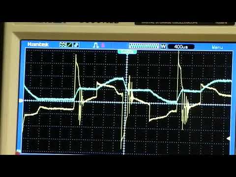
    The last post presented preliminary data and performance of the ZFM utilizing the R Cole CEMF circuit. Inserted below are four pics that depict the oscope graphs for Voltage (yellow trace) and Amperage (blue trace) under a no load condition. The timing here is ~55 degrees advance from the coil end/center of the rotor Neo interface. The ZFM is being powered by 2 LAB's in series for both consecutive test configurations. These tests are in Coil Parallel mode.

    The first pic is of the Parallel run without the CEMF circuit at 24 volts at 8800 RPM and 1.70A, while the second pic depicts Gen mode when the power is removed from the ZFM circuit. The Gen mode trace is in actuality the motor's BEMF and the maximum voltage is about 20v. The BEMF trace is a relatively regular wave pattern.

    You will note in the first pic that the inductive spikes upon removal of power hit nearly 70 volts.

    Click image for larger version

Name:	pic_46_4.jpg
Views:	1
Size:	132.6 KB
ID:	50111

    Click image for larger version

Name:	pic_46_5.jpg
Views:	1
Size:	119.1 KB
ID:	50112

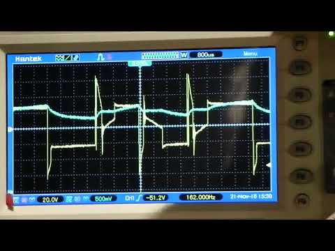
    The third pic displays the Parallel run w/ the Cole circuit at 24 volts at 8800 RPM and 1.67A, while the fourth pic presents the BEMF graph. When the Cole CEMF circuit is activated the major voltage spikes during operation are reduced to a maximum of about 55 volts. The remainder of the graph appears very similar to the w/o CEMF pic. Now the last pic of the BEMF trace is radically different and demonstrates the impact of the rectifier bridge and the 4uF capacitor. Certainly this can be further smoothed by raising the value of the capacitor.

    Click image for larger version

Name:	pic_46_2.jpg
Views:	1
Size:	129.1 KB
ID:	50113

    Click image for larger version

Name:	pic_46_3.jpg
Views:	1
Size:	120.2 KB
ID:	50114

    In conclusion the very tight gap between the rotor and coil along with the stronger Neo's does markedly improve the torque characteristics of the ZFM. The most recent tests in series mode clearly show that the ideal advance for the motor ranges around 45 to 50 degrees. A test run on Feb 7 at 24 volts showed the torque curve to be stable from a no load speed of 4500 RPM at 0.58A down to 2100 RPM at 1.57A with a 615 gram load. Nominal efficiency output/input of 26% without the CEMF circuit (New Bipolar Switch board is on its way).

    Increasing the voltage to 36v will improve the torque and efficiency to 30%. It has been demonstrated that efficiencies of over 40% can be achieved with various timing, rotor and Neo configurations for the Twin coil 4 Neo rotor ZFM. The total impact of the Cole CEMF circuit, from the small test sample, appears to add about a 10% performance improvement.

    So overall the 4 pole ZFM experiments are relatively complete. There may be additional posts to demonstrate relevant results. For now the next steps are to improve the timing method and design the next ZFM configuration.

    Thank you for your attention...
    Last edited by Yaro1776; 02-09-2019, 12:38 PM. Reason: Mode clarification

    Leave a comment:


  • Yaro1776
    replied
    ZFM with R Cole's CEMF Circuit

    Hola to all,

    During Ron Cole's association with John Bedini a number of very interesting motors and control circuits were produced. This collaboration yielded the BiPolar Switching circuit (depicted in prior post) and other enhancements. One of the enhancements was the adder circuit to collect the "Counter EMF" as described by Cole. A better description may be that the terms are not that well defined. It appears, at least to this writer, that the circuit may just be collecting the extra potential created by the inductive collapse upon the removal of power from the coil circuit before the polarity reversal - correct me if I am wrong here. So, it may not be a true BEMF recycling circuit, but an inductive spike collection method. The semantics here can be rehashed by others and corrected as need be. Of more consequence is the impact on motor performance.

    Click image for larger version

Name:	R Cole CEMF.jpg
Views:	1
Size:	250.2 KB
ID:	50089 Click image for larger version

Name:	2018 BEMF.jpg
Views:	1
Size:	14.1 KB
ID:	50090

    The additional circuit is essentially a diode bridge, whose sole purpose is to collect this collapse of potential during coil power off and to transform it into a usable form that can be injected back into the ZFM's coil power circuit. All in all, an interesting conjecture. Question is whether this does indeed work and, more importantly, can it be used to jack up the performance of the ZFM??

    As an example preliminary data from the 4 pole configuration is used:
    Series mode w/o Cole circuit
    36.26v, 6733 RPM at 0.81A, 000 gr Load with input 29.37w - 00.0% eff
    36.83v, 4617 RPM at 1.54A, 540 gr Load with input 56.72w - 28.8% eff
    Series mode w/ Cole circuit
    36.23v, 7180 RPM at 0.79A, 000 gr Load with input 28.62w - 00.0% eff
    36.89v, 4690 RPM at 1.50A, 550 gr Load with input 55.34w - 30.3% eff

    In general from multiple readings in Series mode the added Cole circuit yielded about a 10% improvement.

    Parallel mode w/o Cole circuit
    23.80v, 8340 RPM at 1.46A, 000 gr Load with Input 34.75w - 00.0% eff
    24.29v, 4610 RPM at 2.80A, 550 gr Load with input 67.29w - 24.5% eff

    Parallel mode w/ Cole circuit
    24.39v, 8443 RPM at 1.53A, 000 gr Load with input 37.32w - 00.0% eff
    24.29v, 4950 RPM at 2.69A, 550 gr Load with input 65.34w - 27.1% eff

    In general from multiple readings in Parallel mode the added Cole circuit yielded about a 10% improvement.

    Overall the above experiments were not pushed for more performance and RPM. The last set of experiments were incomplete when a shorted wire from the Cole circuit breadboard fried one set of transistors. This will be repaired and the experiments run again in the future.

    It is of interest that in Parallel mode the 2 wire output from the Cole circuit was 2 to 4 volts higher than the combined input voltage from the Bipolar switch - for a 24.5 V power supply voltage, the total coil voltage potential would equal 49.0 volts, but the Cole circuit output would read 52 volts. This split output was fed into the transistors.

    BTW the function of the 4uf capacitor in the circuit is to smooth out the voltage speed bumps, I believe that a higher value would provide a bit more smoothing. Not sure what the function of the balance resistor is at this time.

    In the next post, as time permits, I intend to more fully describe the performance of the added Cole circuit through a comparison of scope shots with and without the circuit.

    Thanks for your attention...
    Ciao,
    Last edited by Yaro1776; 01-24-2019, 05:37 AM. Reason: data value correction

    Leave a comment:


  • Yaro1776
    replied
    4 Pole ZFM with Big AL2 rotorII

    Hello to Everyone in Legoland,

    For this set of experiments the 4 Pole Rotor in the ZFM is outfitted with four 1"Lx1"Wx1/2"T N52 Neos arranged in a NSNS configuration identical to prior configurations with the exception of the coil to Neo edge gap/clearance. The clearance was reduced to the practical limit of less then 1/16" or 2 mm. The prior rotors had between 0.160" to 0.300" clearance.

    The intention was to see if the ZFM torque curve improved over prior rotor arrangements; in essence, the motor did display a stouter Torque curve in both Series and Parallel mode. The maximum RPM was diminished, however the torque curve was expanded over a wider usable range. The maximum torque value was similar to prior tests, but the overall efficiency of the motor was diminished from the last tests with the 2"Lx1/2"Wx1/2"T rotor.

    The Firing advance setting was restrained for best work performance and not speed. The advance was set a bit beyond than the lowest amperage range read point. This resulted in lower overall speed, but at lower amps. Particularly useful for the parallel mode of operation to minimize transistor overheating at high loadings.

    BigAL2 Rotor:
    Parallel Mode
    23.80v, 8340 RPM at 1.40A and 000 gr Load, 34.75w with 0% eff
    24.69v, 4730 RPM at 2.86A and 510 gr Load, 70.64w with 22% eff
    The efficiency results ranged up to 28%. Transistor heating limited maximum loading

    Series Mode
    40.19v, 7000 RPM at 0.70A and 000 gr Load, 28.10w with 0% eff
    40.90v, 4852 RPM at 1.41A and 530 gr Load, 58.10w with 29% eff
    The efficiency results ranged up to 29%. Transistor heating was not an issue.

    The above performance results are lower than the 2"Lx1/2"Wx1/2"T rotor even though the overall magnetic pull force is identical. The 1.5"Lx1"x1/2" (67.5 lbs pull strength) Neo rotor pulled a 42% eff at similar loads.

    An observation to note is that the 4 Pole efficiency is about twice that of the 2 Pole when the firing rate is 4 times a revolution.

    All the above demonstrates that the magnetic pull force exerted by the Neo has a positive impact on performance. The reduction in clearance does improve the basic tractability of the motor. The length of the Neo also comes into play. The coil clearance is another important factor. Endless possibilities, but the path is clear.

    The basic ZFM configuration is just an introduction. It is not optimized, but it does engage the experimenter whose purpose is gaining knowledge and understanding of the arcane world of magnetic field interaction.

    The next step is to integrate the R. Cole BEMF recovery circuit into the ZFM equation. Will it improve performance? Stay tuned...
    Last edited by Yaro1776; 01-23-2019, 05:38 AM. Reason: 2 and 4 Pole Efficiency

    Leave a comment:


  • Gary Hammond
    replied
    Hi Yaro,

    Originally posted by Yaro1776 View Post
    Hello to all,

    Now that the 2018 holidays gave everything that you desired, it is time to move on to the continuing ZFM saga. This closing chapter will use the previous 2 Pole rotor and add two more opposing Neo's (1"wx1"l x 1/2"t) creating the standard 4 Pole rotor configuration. However, this rotor is larger dimensionally and with the above Neo's the edges clear the coil by about 1/16". Very tight! A difference of nearly 1/8".

    In essence, this is about as tight a Neo to Coil gap as is practical. Ideally a curved arc segment Neo would be the best and offer a tighter gap, but all that is readily available are the rectangular Neo's. It is useful to bear in mind that the greatest magnetic field on a rectangular Neo is the center of the pole face. The performance of this configuration will be compared to prior test data to observe if any gains are realized through the gap reduction.

    Since this is, perhaps, the final effort with the 4 Pole configuration, particular attention was paid to minimizing the bearing friction and perfecting the alignment. The initial proofing runs yielded 8800 RPM at 1.55A and 24.65V (LAB power) in Coil parallel mode. The transistors remained at skin temperature.

    Another adder to this configuration will be a BEMF recovery circuit as described by R Cole's circuit schematic. It will be interesting to experiment with the tighter gap and the BEMF circuit. See below.
    [ATTACH=CONFIG]7206[/ATTACH]

    Enough for now and Happy New Year,
    This sounds very interesting. I'm anxious to see the results.

    By the way, I found some curved magnets you might be able to use on the magnet4less web site. Here's the link. http://www.magnet4less.com/product_i...oducts_id=1199

    Leave a comment:


  • Yaro1776
    replied
    4 Pole ZFM with Big AL2 rotor

    Hello to all,

    Now that the 2018 holidays gave everything that you desired, it is time to move on to the continuing ZFM saga. This closing chapter will use the previous 2 Pole rotor and add two more opposing Neo's (1"wx1"l x 1/2"t) creating the standard 4 Pole rotor configuration. However, this rotor is larger dimensionally and with the above Neo's the edges clear the coil by about 1/16". Very tight! A difference of nearly 1/8".

    In essence, this is about as tight a Neo to Coil gap as is practical. Ideally a curved arc segment Neo would be the best and offer a tighter gap, but all that is readily available are the rectangular Neo's. It is useful to bear in mind that the greatest magnetic field on a rectangular Neo is the center of the pole face. The performance of this configuration will be compared to prior test data to observe if any gains are realized through the gap reduction.

    Since this is, perhaps, the final effort with the 4 Pole configuration, particular attention was paid to minimizing the bearing friction and perfecting the alignment. The initial proofing runs yielded 8800 RPM at 1.55A and 24.65V (LAB power) in Coil parallel mode. The transistors remained at skin temperature.

    Another adder to this configuration will be a BEMF recovery circuit as described by R Cole's circuit schematic. It will be interesting to experiment with the tighter gap and the BEMF circuit. See below.
    Click image for larger version

Name:	Bedini Cole Bipolar Switch.jpg
Views:	1
Size:	103.7 KB
ID:	50083

    Enough for now and Happy New Year,

    Leave a comment:


  • Yaro1776
    replied
    Two Pole Rotor ZFM Experiments VI

    November ended with a body slam of 16+ inches of damp snow that knocked out power and comm for 72 hours - this effectively delayed the following post until now.

    The change to the Timing Rotor Neo configuration to NN was a great improvement in overall performance yielding the following data:

    Coil Serial Mode: 35.86v 8294 RPM at 1.10A

    Click image for larger version

Name:	pic_31_1.jpg
Views:	1
Size:	129.6 KB
ID:	50073

    Coil Parallel Mode: 24.5v 8571 RPM at 2.90A

    Click image for larger version

Name:	pic_31_10.jpg
Views:	1
Size:	134.7 KB
ID:	50074

    Inspection of the above O-scope pics demonstrates the changes in the coil firing, for both modes, to a more regular pattern. Later, the Reed switches were further tweaked manually for a better equality of the dead time between firings.

    This should finish out this round of 2 Pole ZFM configuration experiments and the results were certainly worth the effort as follows:
    1) It was demonstrated that the opposing 90 degree empty segments of arc without a coil do not appear to negatively impact performance. The unusual characteristic of the empty arc segment yielding a greater RPM than the Coil segment when one leg of the firing circuit is disabled. This aspect was repeatable on multiple occasions.

    2) The modification to the Neo configuration, from a N-S opposing pattern to a N-N opposing pattern, demonstrated that the magnetic field interplay between the ZFM Motor and Timing Rotor are very important for maximum performance. It appears that the Motor Rotor Neo's play an important part in the 2 Pole arrangement and do influence the Reed switches and timing.

    3) The 2 Pole ZFM will produce enough torque to drive a modest load, albeit not very efficiently.

    Next on the agenda is to modify the existing Motor Rotor to a 4 Pole configuration - the upcoming Holidays will undoubtedly delay this a bit.

    Happy Holidays...

    Leave a comment:


  • John_Koorn
    replied
    Still reading with interest Yaro

    John K.

    Leave a comment:


  • Yaro1776
    replied
    Two Pole Rotor ZFM Experiments V

    Hey Gary,

    Appreciate your positive comments.

    I can only speculate about the magnetic spins. The deeper question for the 2 Pole is the constant coil polarity reversals (reversing at 480/sec at 7200 RPM) along with the rotating North facing out rotor Neo's, which also create a fairly influential axial field. Somewhat difficult to have a good perception of how both fields mesh, but experimental results certainly indicate that the timing rotor field can impact performance.

    I have demonstrated via screen shots, in previous posts, the firing (Coil energizing) irregularity. This has been a thorn in my side for a couple of months - after the Turkey fest it occurred to me that perhaps the small Timing Rotor Neo's were the root cause. The two TR Neo's were setup in a N-S opposing config for 4 Pole rotor operation.

    Inspection of the screen shots display a dual pattern of firing on time. One set is short while the other set is longer for 4 firings per revolution. That behavior suggests that there is a definite conflict between the ZFM's magnetic fields.

    So, the Timing Rotor Neo's were modified to a N-N configuration to reduce one area of magnetic field conflict. Completing this modification this morning and performing several operational tests verified that timing is now regular. Both positive and negative polarities, now display, essentially, the same interval for coil-on time.

    This simple mod does demonstrate that the rotor axial field has a large influence on the Timing Rotor and reed switches. I will post the screenshots and numbers of this mod in the next day or so - important information with respect to the influence of the axial rotor magnetic field.

    Certainly, the above is way too much information for the casual lurker, but then again, this is just documenting ongoing test results for a global audience and the experimenter's personal log.

    Happy Black - Cyber Saturday,
    Last edited by Yaro1776; 11-24-2018, 03:05 PM.

    Leave a comment:


  • Gary Hammond
    replied
    Hi Yaro,

    Happy Thanksgiving !!

    I've been enjoying your research with the ZFM. Very interesting results. Especially the observation that the rotor is being driven by the coil ends rather than only within the coil. John always said the rotor rides on the magnetic spins; so I assume the spins are replicated between the coils as well, when the coils are properly spaced ??

    Leave a comment:


  • Yaro1776
    replied
    Two Pole Rotor ZFM Experiments IV

    Next Video of Parallel Mode.


    Happy Turkey

    Leave a comment:


  • Yaro1776
    replied
    Two Pole Rotor ZFM Experiments III

    Hello to All and Happy Thanksgiving,

    The Two Pole experiments have been an interesting diversion. The results of this testing have demonstrated that the lack of four coils in the this ZFM configuration do not appear to appreciably alter the operational characteristics and reinforce the point that the motive force for the motor are the coil end points. The area of greatest electromagnetic force is still there even when the coils are powered when the rotor Neo's are outside of the coil itself.

    This was demonstrated in series mode when one leg of the coils' was disabled. Energizing the coils when the rotor was within the coil or outside of the coil did not yield any major differences in performance.

    The torque test of this 2 Pole configuration was completed only for Series mode at 36v. Parallel mode torque testing was scrapped due to rapid overheating of the board transistors.

    RUN 1 - 5673 rpm, load 150grams; Input 46.38w; Output 5.54w; Eff 11.95
    RUN 2 - 4784 rpm, load 225grams; Input 55.78w; Output 7.01w; Eff 12.56
    RUN 3 - 3837 rpm, load 325grams; Input 66.98w; Output 8.12w; Eff 12.12
    RUN 4 - 6710 rpm, load 0grams; Input 37.80w; Output 0.0w; Eff 0.0

    Not overly impressive, but bear in mind the timing and firing issues do have a major impact. Irrespective, this 2 pole configuration can still drive a load.

    To finish up this Holiday missive are two videos (15.1 and 15.2) of the 2 Pole ZFM configuration in Parallel and Series mode - second video is in the next post:


    Until next time....

    Leave a comment:


  • Yaro1776
    replied
    Two Pole Rotor ZFM Experiments II

    The prior post depicts the behavior of the Two Pole Series configuration along with some general performance data.

    BTW - the value for the amps (blue line) is calculated by taking the millivolt differential from a base of 2.5V (positive or negative value) and multiplying by factor of 9.6. Hence, a 500 mV differential value is equivalent to 4.8A.

    Pic 1 demonstrates the coil firing pattern and one will note the irregularity of the firing timing. The coils are fired by reed switches every 90 degrees and actuated by a Timing Rotor with accurately spaced 1/4" Neo's 180 degrees apart. Previous experience has demonstrated that this method works well, however with the Two Pole arrangement this is not the case since it is obvious from the Oscope Pic that the firing is irregular or of varying frequency.

    To eliminate this, the timing assembly was modified using 3 different Timing Rotors and 2 different Reed mounts. The results demonstrate that the firing frequency and basic voltage/amp graphs' shapes were unaltered by these changes. Same same!

    Note the voltage rise time during firing - nearly instantaneous for the air coil.

    Pic 2 depicts the generator mode behavior as the Rotor Neo's pass through the coil segment creating a positive voltage and a negative voltage through the 90 degree empty space segment without any current. This graph is very regular with respect to timing as the Neo's travel by the coils.

    Pics 3 and 4 depict operation with one of the two legs of the timing circuit disabled. Of major interest is the detailed look at the BEMF and ringing behavior of the voltage. Perhaps it is time to add a diode bridge to the BiPolar switch board when running with the LABS and harvest these voltage spikes- not recommended for the 120v Power Supply.

    Okay, so now how does the Parallel Coil mode look when running - here are the Oscope Pics:

    Pic 1 24.0v at 1.92A and 7133RPM. The operational voltage is approximately one half of the series voltage and the amperage is approximately twice the series amps. You will note that the Pics for this mode are very similar to the prior post's Series configuration. The transistors heat up rapidly and only allow a short period of operation. Very hesitant to do a torque test due this rapid heating.
    Click image for larger version

Name:	2 Pole Par Coil AL TR5 PS.jpg
Views:	1
Size:	142.0 KB
ID:	50060

    Pic 2 Running at 24v with one leg disabled - motor slowed way down to under 1000 RPM - very rapid heating of the firing transistors with amperage maxed out at nearly 5 A. Used 24v LAB for this run. Regular Power Supply a bit flakey here.
    Click image for larger version

Name:	2PPar_one_leg.jpg
Views:	1
Size:	117.9 KB
ID:	50061

    The next and last post of the Two Pole experiments will present the results of the Series Coil Torque tests and perhaps a video of the Series and Parallel Coils in operation.

    Happy Deer hunting season...
    Last edited by Yaro1776; 11-16-2018, 06:05 PM. Reason: Missing Pic Links; Correct rest voltage value

    Leave a comment:


  • Yaro1776
    replied
    Two Pole Rotor ZFM Experiments

    November Greetings to All,

    Back in the experiment mode after a busy Summer and Fall hiatus. Definitely a good opportunity to clear the head and start afresh with the next ZFM episode.

    The new Oscope has been a great addition to the test instrumentation and has yielded satisfactory results to date, in particular when examining the firing characteristics of the ZFM in the following experiments.

    The initial thrust of the 2 pole experiment was to investigate the behavior and operational characteristics of the standard two 90 degree opposing coil ZFM in two modes of operation with a series Coil configurattion. Normally a coil is energized when the Rotor's Neo magnets are within the coil, however in this instance the coils are energized both within the coils and external to them. The coils are energized 4 times a revolution. A second variant of 2 energizings per revolution was also run. Please note that this configuration has a very tight gap of ~0.040" between the rotor edge and coil.

    The first pic demonstrates the 4x mode at 45.98v at 0..92A ad 8491 RPM. The higher voltage was used to demonstrate the voltage (yellow line) and amperage (blue line) values in more detail.
    Click image for larger version

Name:	pic_15_3.jpg
Views:	1
Size:	137.2 KB
ID:	50053

    Pic 2 demonstrates the generated voltage created by the ZFM when the power is off to the coils and freewheeling.
    Click image for larger version

Name:	pic_15_4.jpg
Views:	1
Size:	121.0 KB
ID:	50054

    Pic 3 demonstrates one leg of the firing circuit only; at 48.48v at 0.72A and 5899 RPM. The rotor is within the coil when energized. Coils are energized 2x per revolution.
    Click image for larger version

Name:	pic_15_7.jpg
Views:	1
Size:	135.7 KB
ID:	50055

    Pic 4 demonstrates the other leg of the firing circuit only; at 47.94v at 0.74A and 6386 RPM. The rotor is in the 90 degree empty space between the coils. Coils are energized 2x per revolution.
    Click image for larger version

Name:	pic_15_8.jpg
Views:	1
Size:	129.6 KB
ID:	50056

    So the above demonstrates that the coil end points are the true drivers of the ZFM in the present configuration. It is interesting to note that the RPM is higher during the empty space firing. This was observed several times under several different voltages, firing angles and advances.

    Feel free to comment...
    Last edited by Yaro1776; 11-14-2018, 12:48 PM. Reason: Add Series Coil config clarification

    Leave a comment:


  • Yaro1776
    replied
    Thanks for the interest John,

    Originally posted by John_Koorn View Post
    Hi Yaro, it's unfortunate that the rotor is toast. I sincerely hope no one was injured! Rotors can be rebuilt - eyes on the other hand, cannot.

    John K.
    I definitely was pushing the envelope with that particular test at maximum advance and 36v in parallel coil mode. Bear in mind that in parallel mode the current/voltage affect to the coils is similar to 72v in series mode. Normally in series mode the max voltage threshold is 48v for obvious safety reasons. One can only speculate as to the forces generated at that high a voltage hammering the rotor Neo's 800 times per second at 12,000 RPM.

    A walk on the wild side,
    Yaro
    Last edited by Yaro1776; 09-15-2018, 04:41 AM. Reason: clarification

    Leave a comment:


  • John_Koorn
    replied
    Hi Yaro, it's unfortunate that the rotor is toast. I sincerely hope no one was injured! Rotors can be rebuilt - eyes on the other hand, cannot.

    John K.

    Leave a comment:

Working...
X