Hi Yaro,
As I wait for the components to arrive from Digikey to build the Bipolar Switch, I got to thinking about how I will mount the devices to a heatsink. I don't plan on the transistors getting very hot but want the safe guard there incase something happens. Anyway, from looking at Peter's ZFM build, the transistors seem like they are just glued to the heatsink somehow. I'm not sure how exactly they are attached but am wondering if anyone here has any insight into that.
Also, regarding the circuit construction, I see that the leads of all components are as short as possible and everything is soldered together with no PCB. Would it really be that bad to design a PCB with large trace width and minimal trace length? I mean, with EasyEDA its so easy to do. I will likely try both but wanted to bounce this off the forum aswell.
Lastly, referencing my model ZFM, what would be the best direction to go in as far as adding a generator on the shaft? Should I just print myself a small axial generator? Or wait till my next larger build and try a dc motor or car alternator?
Thanks for your help.
-J
-
The ZFM design should be scaleable to a larger rotor diameter. The question about multiple coils/poles becomes a bit more complex if one is to use the original Bedini concept. Going to 6 poles changes the rotor magnet Neos to opposing polarities similar to Ron Coles work - remaining true to the Bedini magnet/coil config would require an 8 pole rotor.Originally posted by Joster View Post
From last year, the initial trials of the Ron Cole opposing polarity rotor Neos using a 2 pole rotor (N-S config) demonstrated somewhat different operational characteristics. In essence, a simplified experiment of his 6 pole design. This experiment will be run again this fall for a more thorough look at the opposing polarity design.
The timing and duty cycle of the coil energized period are critical.
So is there a tangible difference between both approaches? To be determined.
BTW all your pictures documenting your build in one folder is a nice touch. I do have a number of other ongoing projects that are occupying my attention, so any replies on topic may be somewhat delayed and as time permits.
Keep up the good work Joseph,Leave a comment:
-
the wire gauge is 22AWG and each coil is about 8 ohms
the magnets i used are here:
https://www.amazon.ca/gp/product/B07...?ie=UTF8&psc=1
there are five of these disc magnets stacked for each pole
If you where to imagine a larger ZFM how would it look? larger rotor and coil with more poles? maybe multiple rotor and coils?Leave a comment:
-
Hey Joster
You are off to an excellent start with your build. The 3D parts in your pics look great and are beefy, for sure. When you get around to it detail the coil wire #AWG used (#18?) and Neo size.
The turn-on voltage spike on the o-scope looks to be fairly healthy...
Thanks for sharing your progress,Leave a comment:
-
All sounds great! Here are a few pics showing where im at. I have inly been at this since buting yiur presentation last week. Much more to come.
https://drive.google.com/folderview?...Txn4sG5omBEW8Q
I have five of those neo disc magnets stacked for each pole - NSNS config.Attached FilesLast edited by Joster; 08-17-2019, 06:43 AM.Leave a comment:
-
-
Joster,
Thanks for the positive feedback on my ZFM presentation - assume you meant ESTC 2018. Anyway, it is encouraging to read that you are doing a ZFM build and using a 3D printer for the parts - good of you to offer assistance on the 3D printer end, may be very useful. Your electronics experience may come in handy as the opto timing end starts coming together. The reed switches are OK for the simpler builds, but leave a lot to be desired when the timing and duty cycle require more precision/adjustment range.
The torque testing is an integral part of defining the developed power characteristics of the ZFM and overall performance of any build. Pain in the butt to do all this, but an essential part in evaluating the progress of design modifications. The original torque testing device, while very simple, has almost reached its applied load limit. The next step here is to design a Prony brake for this application - just one of the projects for the winter test program.
If you have any relevant questions with respect to design and operational parameters, well feel free to ask and I will attempt to answer them.
Good luck with your ZFM project!Leave a comment:
-
Hey Yaro,
Your ZFM presentation from the 2019 ESTC is outstanding. I am just working on reading through this thread but wanted to let you know I am following this closely. I am working on building my own and am almost done. I'll upload some pics and vids when I can. I have a good 3d printer which is a big help. If you ever need anything printed up I am happy to help. I also have 10 year experience with electronics and am very comfortable building the H-Bridge/Bi-Polar circuits so I can always help you with that as well. I am very happy to see you doing alot of torque testing. Extremely interesting stuff!
Talk soon,
-JLeave a comment:
-
ZFM Coils Powering a Buck Boost Supply to run a 120 Volt Light Bulb
Greetings --
It been a while since I have posted anything here on the Energy Science Forum. I have not stopped doing research for the quest of generating power to run a useful device. Check out my new video showing the usage of the power off the ZFM coils.
Power Input: Three 100 watt solar panels wired in series that will put out 66 volts at 4 amps in full Sun.
(I measured maximum 55 volts in the Sun at 12 noon EST in Maryland.)
Power Output: Power off the ZFM coils was powering a 50 Amp Full Wave Bridge.
Power Input Buck Boost: 10 volts up to 60 Volts input.
Power Output Buck Boost: 90 Volts up to 120 volts.
Light Bulb used: 120 VAC 6 Watt LED Light Bulb. (Day Light 5000K)
The LED light bulb will not light up if the output voltage from the Buck Boost fell below 87 volts.
Hope you enjoy the video.
-- James
https://youtu.be/-sDcE_xCZS4
Leave a comment:
-
ZFM Multi Voltage Torque Test
Hello to all,
To close out the long running test program of the original YZFM motor a series of torque tests were executed to demonstrate that one of the ZFM design goals was achieved. The final rotor design remained 4 pole with 1"LX1"Wx1/2"T N52 Neo's, but the coil to Neo edge gap was minimized to the practical limit of about 0.040" with an overall duty cycle of 65%. The timing advance is about 50 degrees. As the gap is minimized the Neo magnet edges begin to play a much greater role in the timing and performance. The torque characteristics of the motor are greatly enhanced with this approach with a reduction in achievable maximum speed.
The Torque test was designed to have a constant torque load of 0.31 ft-lb applied to the motor shaft for the voltage range of 24v, 36v, 48v and 60v. In every instance the input voltage, amperage, RPM and load were recorded. In addition, the BiPolar switch was outfitted with the R. Cole inductive spike recovery circuit fed back to the input side of the BP switch.
For reference purposes the unloaded performance for each voltage is as follows:
24.0v 4890 RPM at 0.71A
36.0v 7200 RPM at 0.80A
48.0v 9800 RPM at 0.90A
60.0v 10800 RPM at 1.02A
The first test under load was for 24v - an acid test for the ZFM with a loaded cold start. The test progressed sequentially through the voltages. The basic performance parameters under the constant load of 0.31 ft-lb are as follows:
24.0v 2466 RPM at 1.45A
36.0v 4425 RPM at 1.54A
48.0v 6088 RPM at 1.57A
60.0V 7625 RPM at 1.56A
The nominal output/input efficiency hovered at about 30%. So review the test video via this link:
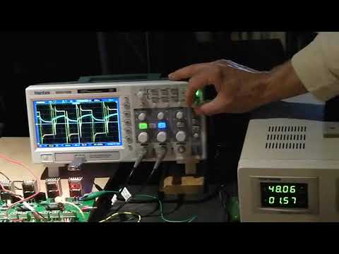
The video presents the YZFM operating under load and at the tail end of the video at 60v one leg of the BP switch is disabled. The YZFM continues to run, albeit at a reduced speed and amperage - this can be duplicated at the lower voltages, though some reduction in load is required. During the one leg operation one will note that the underlying BEMF voltage is visible on the Oscope.
The last part of the video demonstrates the BEMF curve with the spikes from the Cole circuit when the input power is off. This BEMF curve is much more dramatic upon shutdown when the ZFM is unloaded.
BTW, after the video was completed another test was run at 60v at a torque load of 0.46 ft-lb yielding:
60.0v 6490 RPM at 1.97A with about the same efficiency. The motor coils were starting to get warmish.
Thank you for your attention,Leave a comment:
-
By larger coils, I mean overall just having a much larger build like a 12" diameter rotor.Originally posted by Yaro1776 View PostLeave a comment:
-
ZFM Big Coils
I am not sure what you mean by "larger Coils" - is it dimensionally or thicker wire or both? J McDonald's ZFM used fat wire (#16 versus #20) single strand for each coil. In the JZFM limited testing of 4/28/18 at my Vermont lab, we did see the performance and efficiency improve as we raised the voltage from 24v to 42v. We were unable to push it further due to the limits of the torque testing rig. There were a couple of other quirks with this ZFM that have not been investigated to date. Unfortunately, James lives 500 miles away from my northern lab and as yet we have not been able to do another more complete round of JZFM tests. The results data sheet of the JZFM was shown in a slide towards the tail end of the 2018 conference Hidden Dance presentation.Originally posted by Aaron Murakami View Post
You have made some good points here and it is noted!
Thanks for your thoughts and suggestions...Leave a comment:
-
I think the higher voltage experience you have might apply to a smaller motor but it may change as it is scaled up.Originally posted by Yaro1776 View Post
With larger coils, the recovery becomes more significant.
Also, with higher voltage and scaling up - a 2 volt drop on a component for 12 volts is 17% loss but a 2 volt drop on a component for 60 volts is only 3% loss - for example of one way higher voltages automatically could translate to higher efficiencies.Leave a comment:
-
RS,
Definitely good feedback with respect to the timing magnets - confirms my observations by a separate source, though with a different motor.
The three coil and six Neo rotor ZFM design is definitely on my design list for a major trial configuration. It certainly is applicable in this instance - it makes sense. I intend to stick with JB's concept of a wide dead space between the motor coils for the time being with the R. Cole 6 coil config as a backup method.
There is no rush here with that experimentation for the time being, since my attention has been focused on the Bemf of the ZFM. Manipulating the impact of the Bemf upon motor performance has certainly been a very interesting diversion - much to be learned from this black-hole. I may share these particular experiments and the results in the future as time and/or ambition permits. It is all very arcane, and perhaps not really of interest to the majority of readers of this thread.
Never a dull moment with this stuff....Last edited by Yaro1776; 04-03-2019, 02:12 PM.Leave a comment:
Leave a comment: